"Plastic Extrusion Machine"
In this project page we are going to discuss our second project, which is the plastic extrusion machine. This project aims to develop a design to do a plastic extrusion machine that uses the plastic waste used in the 3d printing machine we have in our lab. We look forward to have a full design analyze and structured uniquely by ourselves.
INTRODUCTION
Motivation
Our motivation comes from having the ability to design what we have in our mind as an idea, and making it into a reality. As we want to fabricate this machine in order to save the environment by reducing the plastic waste and turning it into a useable object.
Aim of the Project
The aim of this project is to develop a PLA extruding machine which produces filaments used in 3D printing. The source of the plastic used in the extrusion process is used plastic waste in 3D printing. Hence, the project is environmentally friendly which turns the plastic waste into new useable product. We will develop the project with the knowledge of our training in Fab Academy training; using all the technical skills learned such as: 3D printing, CNC machining, Laser cutting, Embedded programming, input and output devices, and other skills too. We will use what ever is useful to use according to the objects we want to manufacture and design. So now we will talk in brief about some theoretical explanation of plastic and plastic extrusion machine. We have chose to talk about plastic to bring to the idea the use and importance to us that we are using plastic as our source in 3D printing.
BACKGROUND
Plastic History
"We all know that plastic has become ingrained in the consumerist lifestyle, but by just how much? The short answer: by a lot. Over 300 million tons of the stuff is produced each year globally. To give you an idea of just how large that number really is, imagine 6,000 Titanic’s (that is the weight equivalent!). It’s a staggering figure, and it begs a very simple question: How on earth??!
History of Plastic Extrusion, Example shapes and sizes. The truth is plastic had very humble beginnings. The first man-made plastic was invented in 1862 by a man named Alexander Parkes, who showcased his new innovation at London’s Great International Exhibition that same year. Derived from organic cellulose (an important part of the cell wall in green plants), the material was able to be molded at high temperatures and maintain the exact same shape when cooled. Although a novel idea that demonstrated huge potential, the company Parkes founded to mass produce his plastic ultimately failed due to poor product quality.
Clearly, more thought had to be put into producing plastic cheaply and efficiently on a large scale. Less than a decade later, those thoughts had turned into reality. One of the first plastics to succeed on a large scale was developed by John Hyatt, and was named celluloid. The first formula was a flop, but after the addition of camphor (a derivative of the laurel tree), celluloid took off. As time passed, other plastics such as PVC, Cellophane, and Bakelite were developed. Before long, the 20th century was well underway, and new plastic formulas and manufacturing processes became common place.
One of the key influencers that gave the plastic industry a 0-60 that would make most sports cars drool was the fact that most other materials had a very hard time competing with plastic in both ease of mass-scale manufacturing and relative cost. When the first plastic combs came out, the combs of the time just couldn’t compete; made out of ivory or other expensive substances, competition was little more than a dream. Plastic was cheap and made for easy product fabrication.
If we jump back to the modern world, plastic is widely available in many forms. In terms of raw material, plastic tubing, sheeting, and other such products are available in almost every home improvement store in America. In terms of finished consumer products, it is rare to find something with no plastic content. Public schools educate students about the stone age, the bronze age, and the steel age in history class – if the 20th century was given an age, chances are it would be known as the plastic age.[1]"
3D Plastic Waste
As of 2015, only 9% of plastic waste is recycled. The rest pollutes landfills or the environment.
But now, several technologies have matured that allow people to recycle waste plastic directly by 3D-printing it into valuable products, at a fraction of their normal cost. People are using their own recycled plastic to make decorations and gifts, home and garden products, accessories and shoes, toys ansd games, sporting goods and gadgets from millions of free designs. This approach is called as DRAM and it is explained in the link shown. DRAM Method Research has shown this approach to recycling and manufacturing is not only better for the environment, but it is also highly profitable for individual users making their own products, as well as for small- and medium-sized businesses. Making your own products from open source designs simply saves you money. And thus the following link is useful to know about the procedure of DRAM.
Plastic Extrusion Machine
To put it in simple words, plastic extrusion is a “high-volume manufacturing process” in which raw plastic is melted and formed into a continuous profile.” Plastic extrusion machinery is useful for speeding up workflow and volume. It’s also great for ensuring consistency through your products, which are made exactly to your specifications every time. Extrusion machines are simple—raw plastic materials go in, your product comes out and is cut to size. But let’s break it down into a little more detail.
Heat Elements and Control Elements
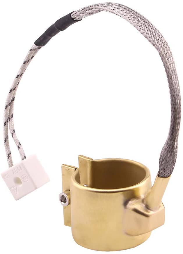
Heat element
Heating elements are the heating elements used in injection machine process. As you can see in the photo below. They come in different dimensions and voltage sizes. These heat elements should be connected to the power source as it shows in the photos.
Control elements
Solid-state temperature sensor
solid-state temperature sensors measure a physical value and then record or otherwise react to it. The sensor (as part of a probe) measures its surrounding temperature. This is done by means of a diode or voltage reference that has a well-established voltage vs temperature characteristic, along with signal- processing electronics to generate a voltage or current output that is proportional to temperature. You can have more information here
Digital Temperature Controller
Digital temperature controller is an essential instrument in the field of electronics, instrumentation and control automation for measuring and controlling temperatures. temperature is displayed on its LCD screen, and you can use it to control the temperature within the preset minimum and maximum range.
Thermometer
The thermometer is the device where you can measure the temperature with, to sense the temperature where the heating elements ( or heater) is reaching to. It is mounted outside the structure of the design.
Pipe
The pipe is the shaft section in our design where the drill bit is going to be inside the pipe to house it. The pipe is could be made of different materials but should be fitted with other parts such as the bearing, the heat elements pads. The material should with stand the heat applied on the structure without any defects.
Die and Tip
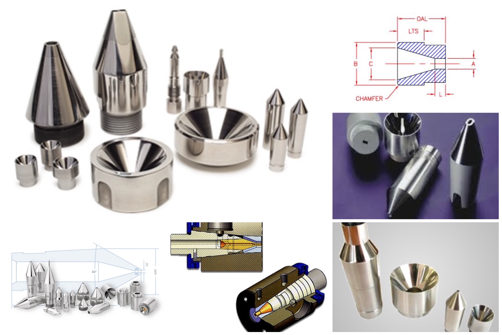
The die and tip is an extrusion tools are commonly used to apply an insulating layer around a solid or stranded wire. The extrusion tip, also called extrusion wire guide, guides a single or group of wires into and through an extrusion. The tip and die is more complicated in shape and fabrication. As shown in the following pictures. They are widely found in the wire drawing machines and other machines that produces plastic filaments wire or materials in circular section shapes. The following photo shows some of the tip and dies shapes.
Structure
The structure in our extrusion machine will be made in general with wood, because wood is one of the best insulators. where it will not increase the heat, thus protects the elements in the extrusion. The structure design will be discussed in the structure design section with all the attempts we made and the design ideas we came to.
Hopper
The hopper is one of the parts in the feed system to the extrusion machine. It is the entry to the structure where you can feed the plastic to it. Hence, having and designing it vary with your need in the structure. The actual extrusion machines, the larger scale ones have bigger hoppers to feed the system which is made of steel. A hopper is a large, pyramidal or cone shaped container used in industrial processes to hold particulate matter or flow-able material of any sort, like dust, gravel, nuts, seeds etc. and can then dispense these from the bottom when needed. Most hoppers are made of steel.
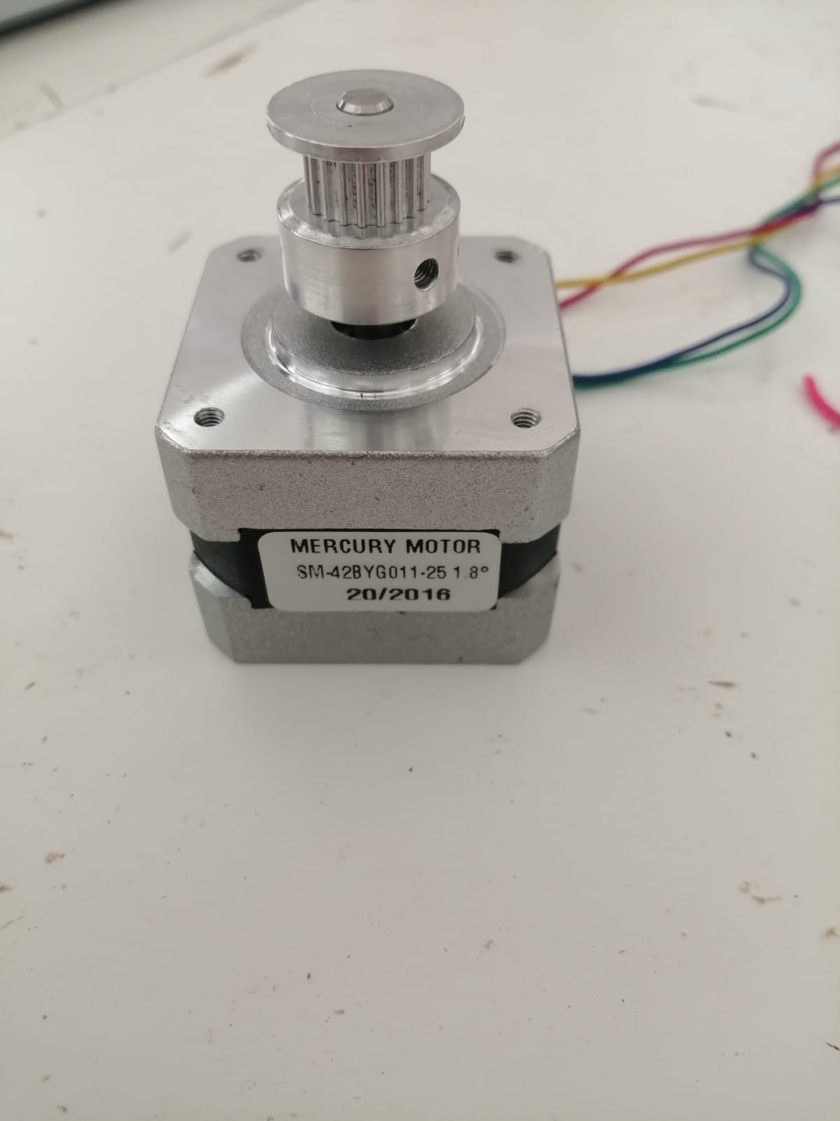
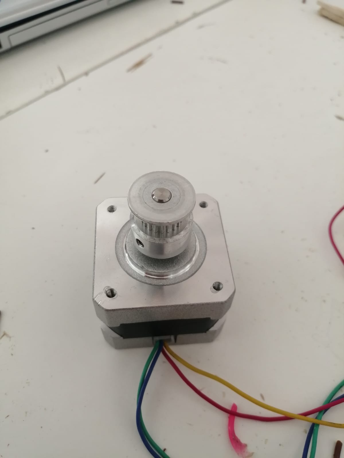
Motor
The kind of motor that we are going to use is stepper motor, this motor will be connected to a coupler that is linked to the drill bit. If the motor rotates then the coupler rotates, by that the drill bit will move inside the pipe to feed the plastic to the heat element section to perform the operation.
Drill Bit
The drill bit can not be designed, but purchased. So we looked for the best drill bit to use in our design. Which is auger drill bit. Auger, tool or bit is used with a carpenter's brace for drilling holes in wood. It looks like a corkscrew and has six parts: screw, spurs, cutting edges, twist, shank, and tang. They are used to drill holes into wood. They are commonly used for boring holes into bulkheads and general timber applications. These drill bits come with a spiral drill bit head which, when drilling, is designed to pull the bit into the wood so you do not have to apply excessive pressure. And they are made with steel. In the design section of the drill bit we will discuss further dimensions and characteristics that we saw perfect to do the design.
Design
Importance of the Design
The design is very important, and especially at our training place which is Fab Lab. 3D printing been one of the most important fabrication tool in the main industry. So having some recycled waste turned into new materials ready to use is very beneficial. Structuring the whole design will let us fabricate and applicate different fabrication techniques in order to understand them in a deeper level. Such as the ones we have discussed earlier.
Used Software
The software we are using to our project is Fusion 360 for the 3D cad designs involved. And Arduino for the programming section of the controlled system. The other program used is CURA for the 3D printing operations. And, MATLAB for the calculations section to our design.
Design Procedure
Our design procedure is the same as the one we followed in project 1. We are going to do the fabrication part in order to know what we are going to use. Calculations and results is done the same, with the MATLAB coding to know the flow characteristics of the fluid used, because we changed our plastic source from regular unknown plastic waste into PLA waste.
// incomplete. please complete it.
Pipe Design
Die and Tip Design
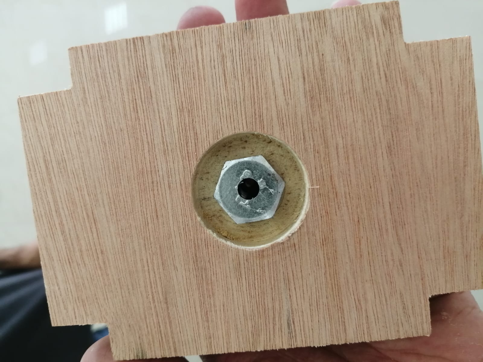
For this part of the design, we are going to make a design for the nozzle used in the extrusion process. A 3D cad design was developed to do the design using FUSION360. We have firstly looked for a design of nozzle where it could be used in extrusion processes so we have developed one using a bolt. The bolt is drilled at the center using a drilling machine in order to do the hole; the hole was about 2mm in diameter. and the following photo shows the design of the bolt we have made
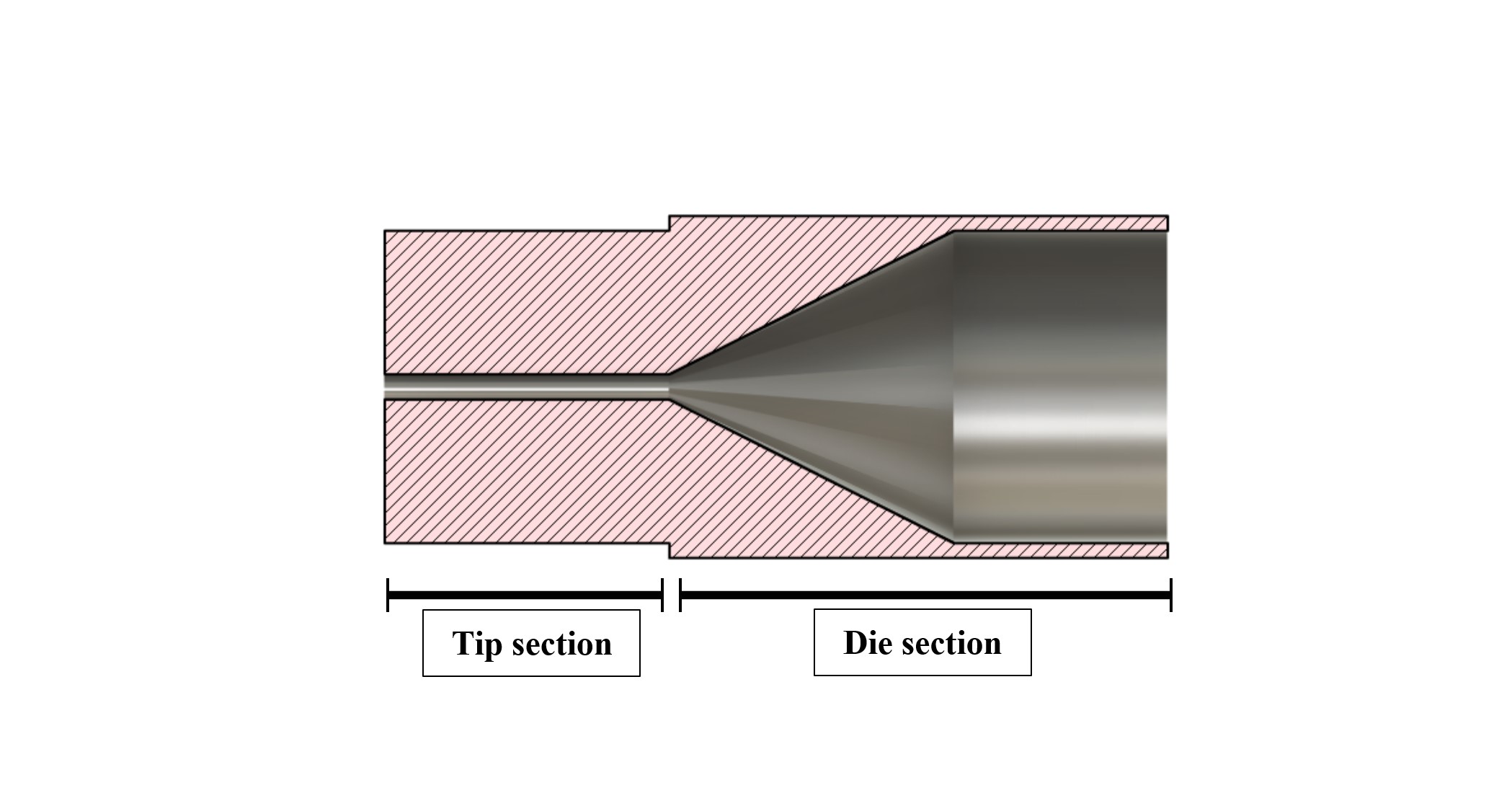
 The bolt did not worked, thus the plastic was not coming of the extrusion machine so we had to do it again using a different idea. All the attempts of the whole project discussed in details in the attempts section of this report page. So for the other attempt we have used a soda can to do a nozzle design, which worked perfectly. Mean while we developed a unique nozzle deign which we called as a "die and tip", this part called as die where it shapes the fluid into the desired shape using a die section and a tip part where the filaments is going to come out. The following photo shows the both sections
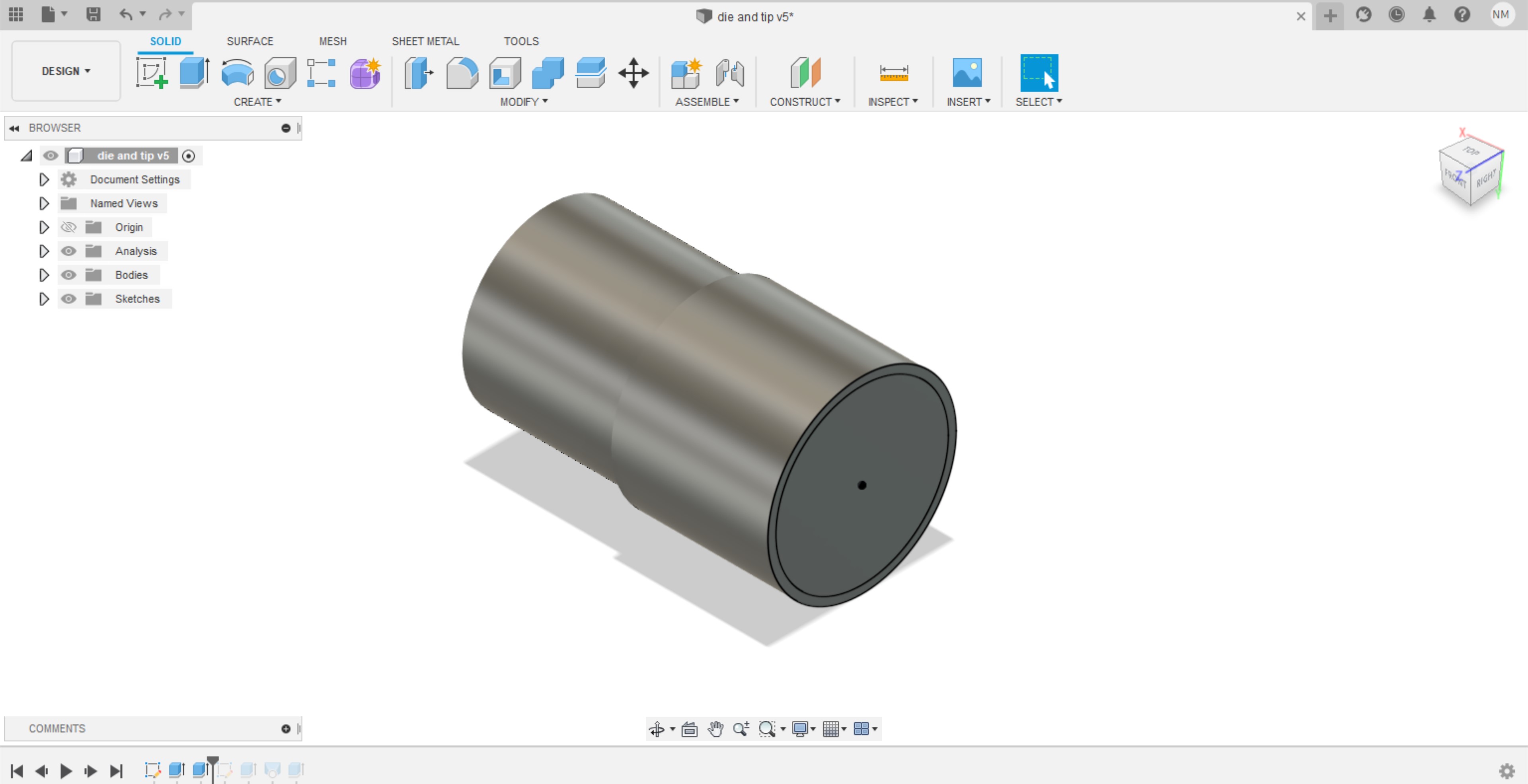
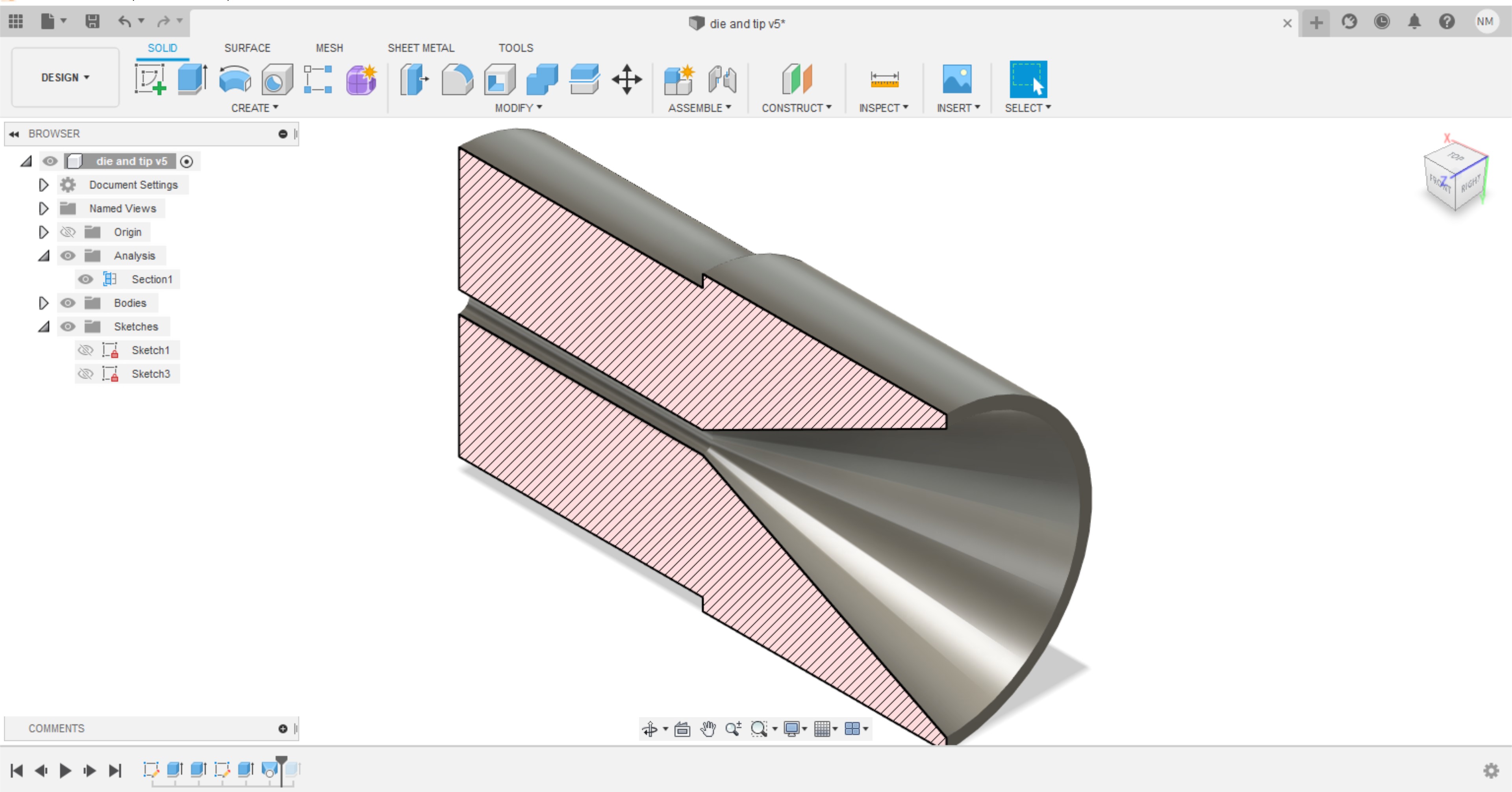
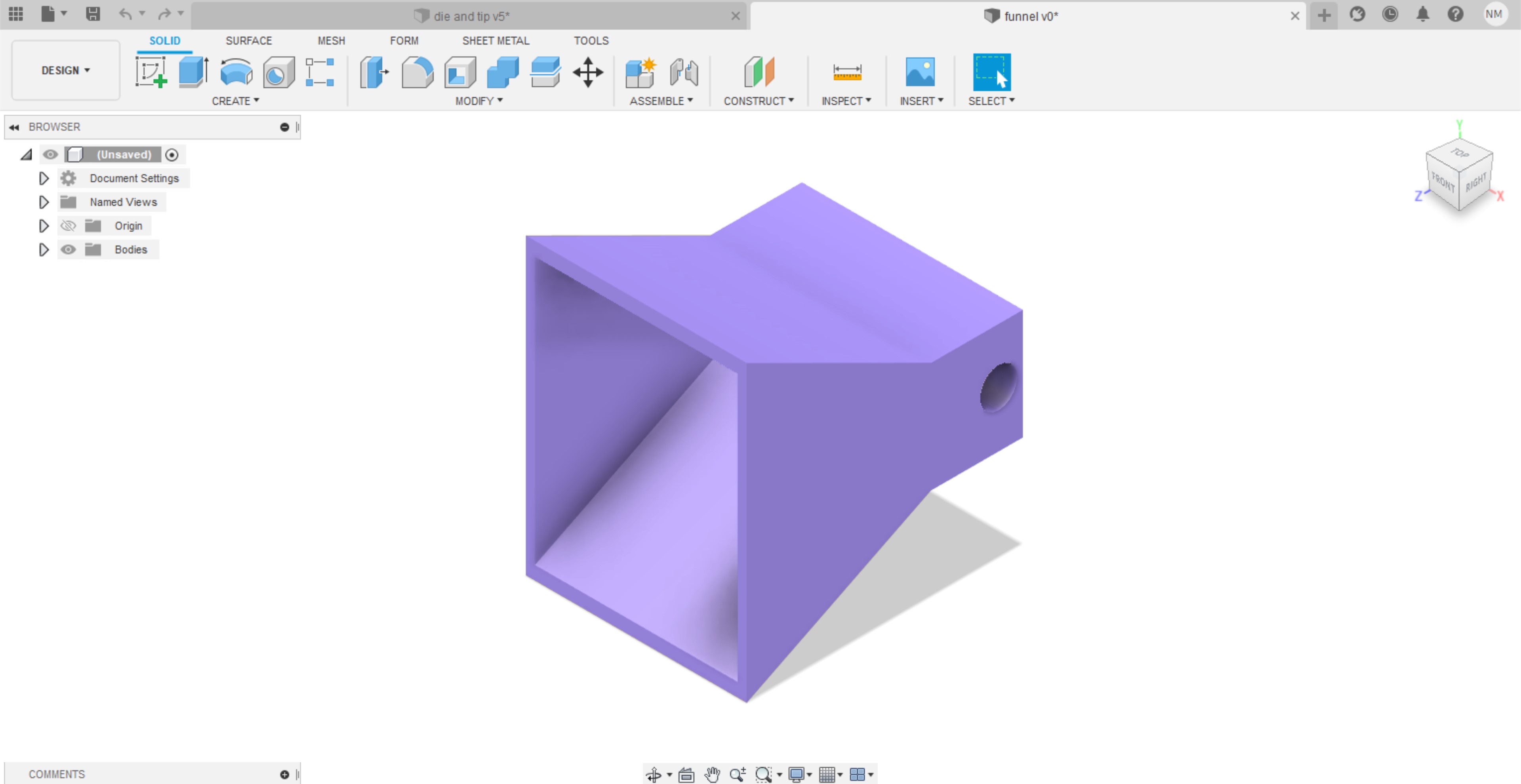
Thus, the following tip and die design is made out of steel the drawing and dimensions. The design is a tip and die where you will be able to fit it to the pipe. The drill bit will reach about the end of the nozzle where you will be able to push all the material through the tip and die section. I have looked for some calculations in order to test the fluid simulation on the nozzle if it works or no. But I could not find any. So I took the risk to design my own design and test it by experimental data first and work the other way around. The time was one of the biggest limitations while designing this nozzle. Because the calculations and the formulas I have looked for nozzles in extrusion machines are more complicated for a bigger scale machines in industry. The following photos show how I worked my way in order to finish my design idea.
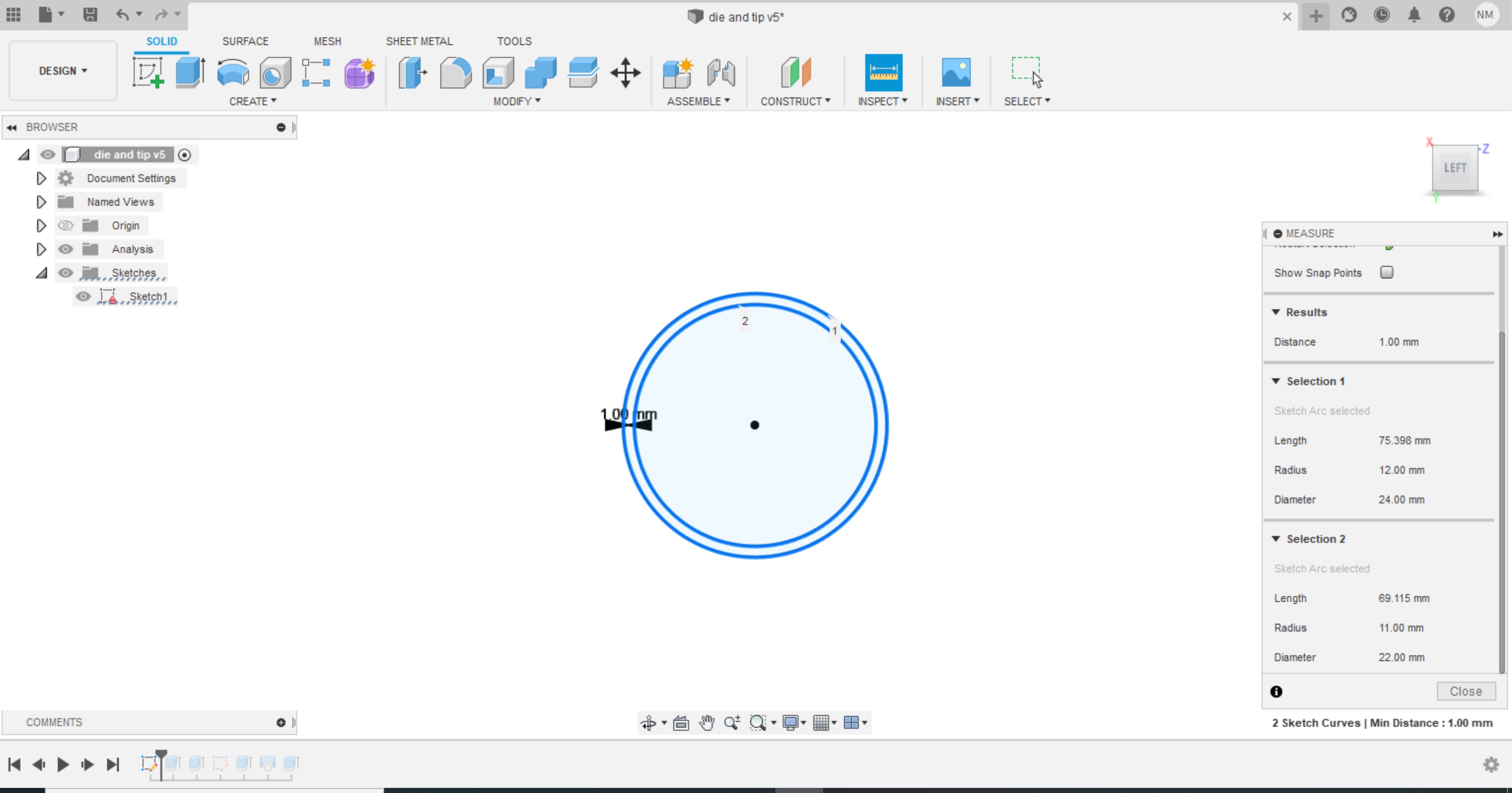
A drawing was made in order to do the outer structure of the tip and die. The dimensions shown in the right tab.
And then extrude the above drawing and had a body like this
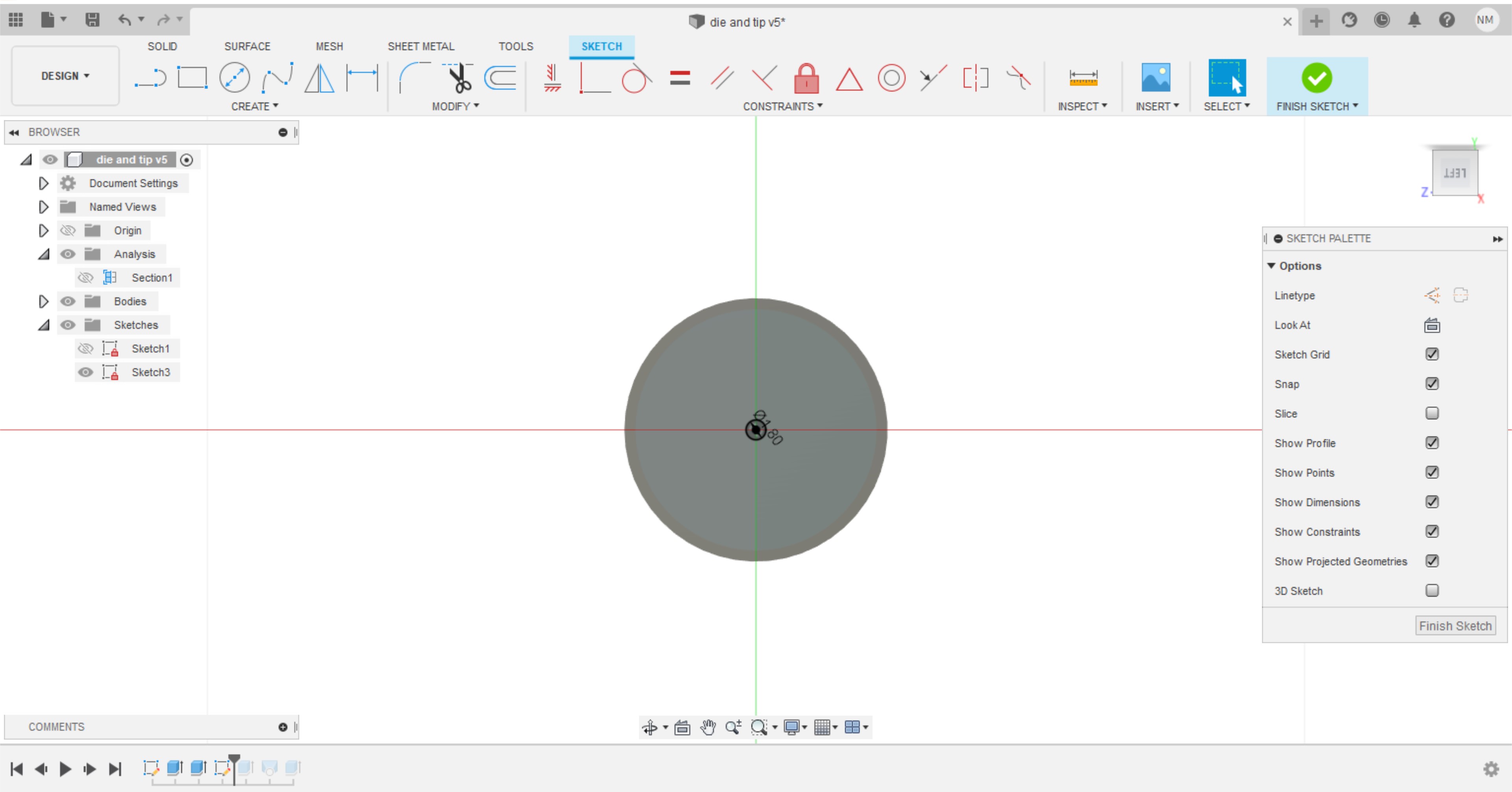
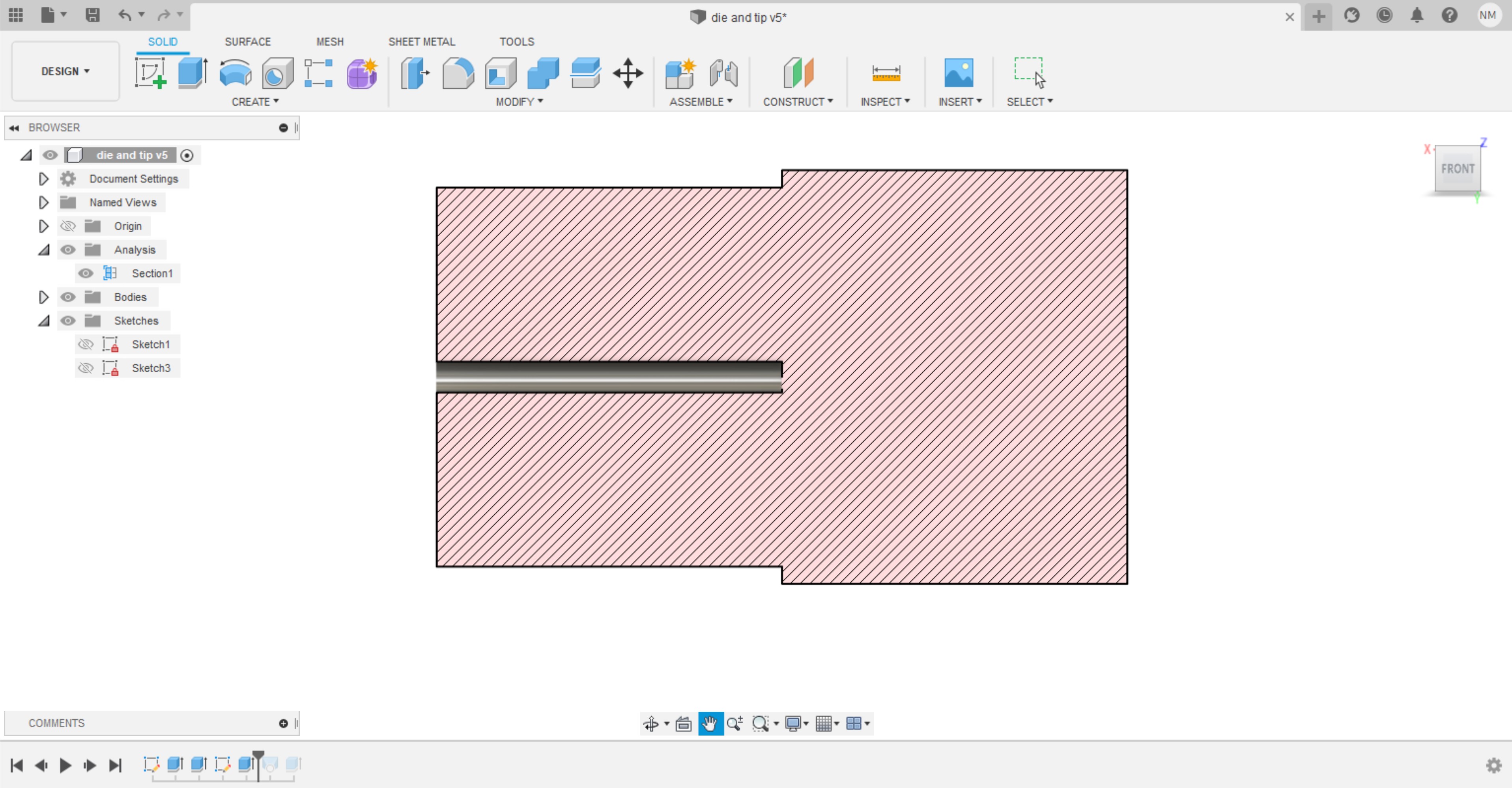
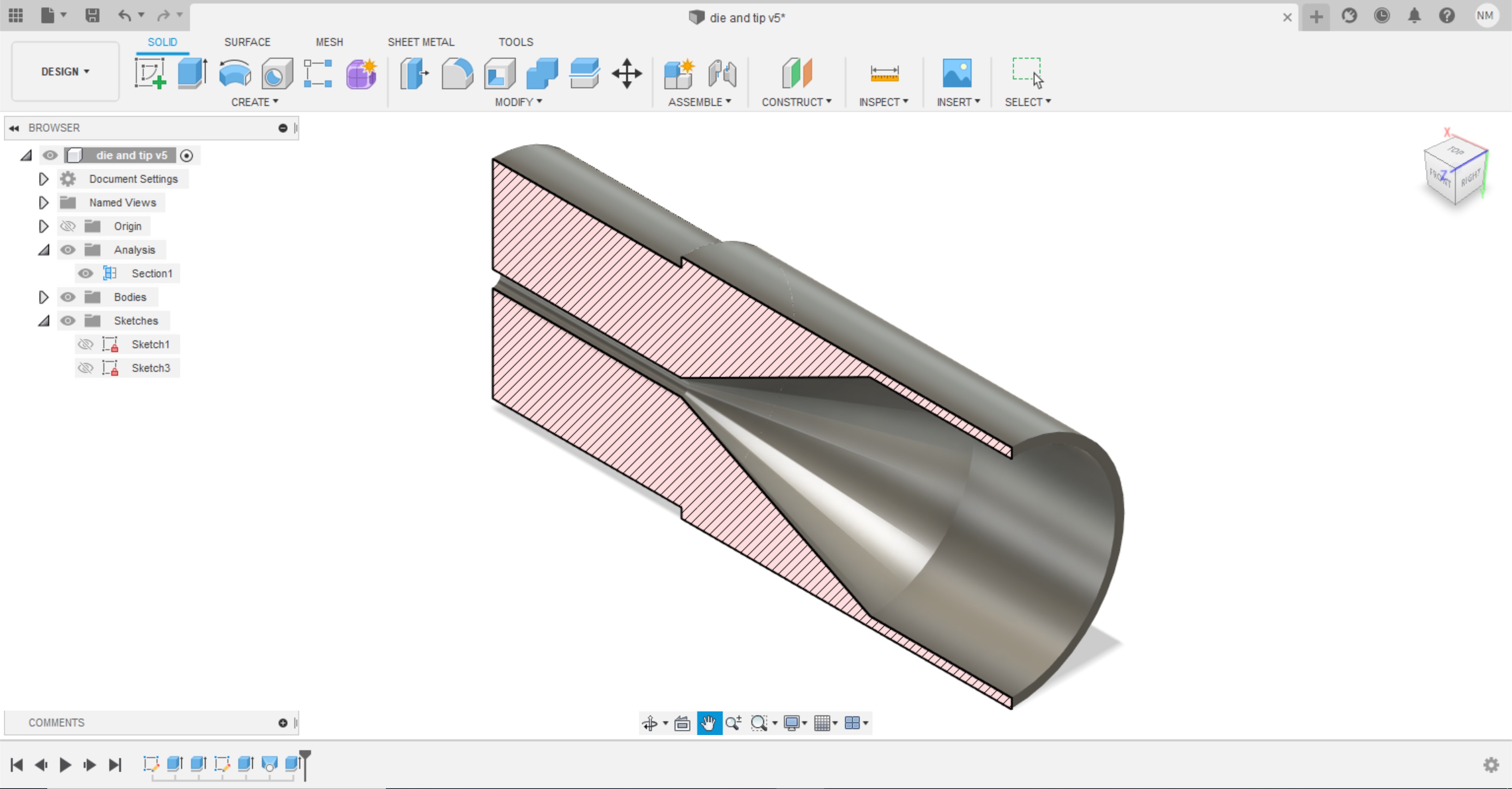
Done a hole on the other side of the cylindrical shaped object, in order to have the nozzle section with a 1.8mm in diameter, it is slightly bigger than the extruder part outside diameter which is 1.75mm. A shrinkage may happen to the plastic with the same range as a difference of 0.05mm. Then I have done an extrude cut to the hole as shown in the section analysis in the third photo.
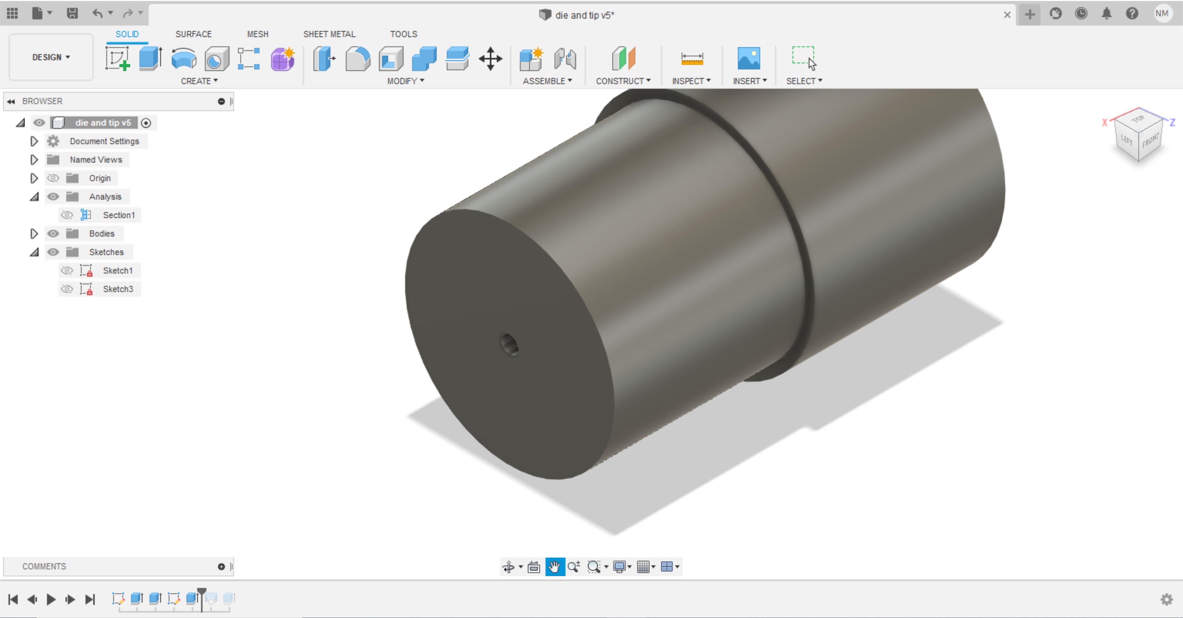
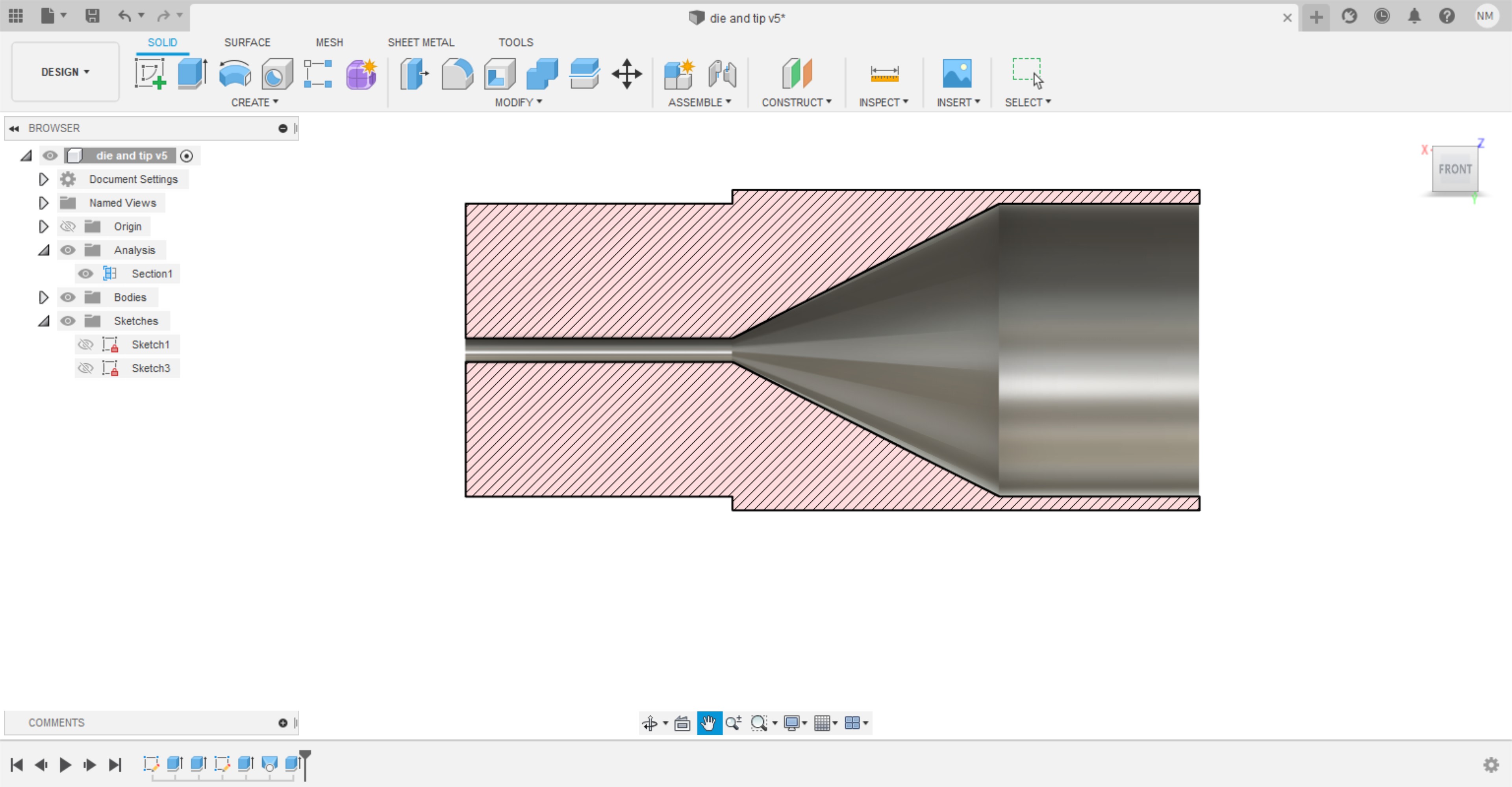
Then I made a loft, and take the cross section of the hole I made and the inner circle I made earlier in the first step.
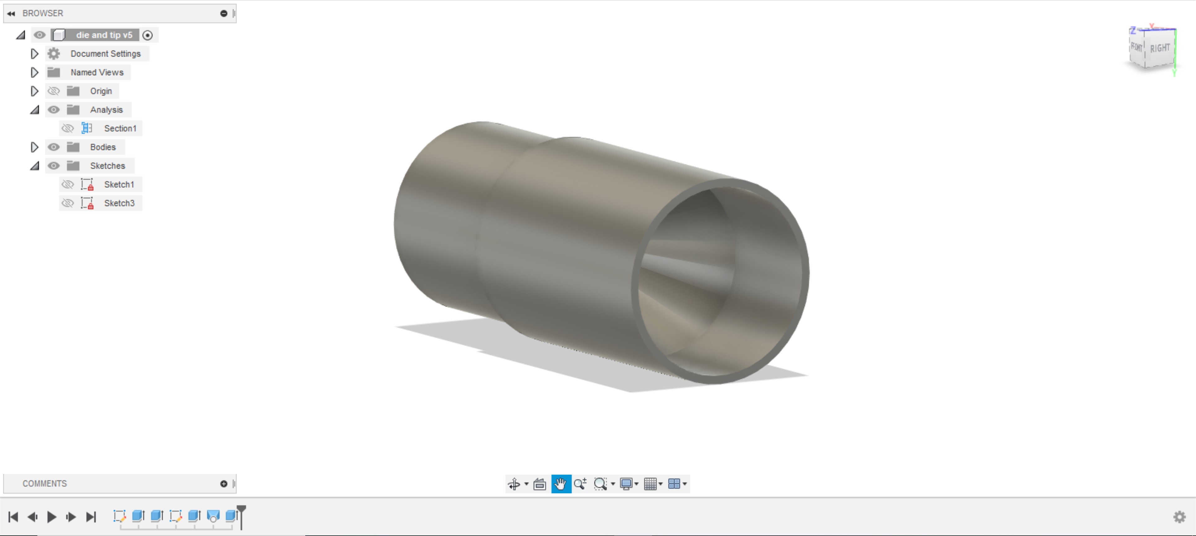
Finally I made an extra extrusion to the side so the pipe can be fitted nicely, as you can see in the following screenshots.
Structure Design
Drill Bit Design
Hopper Design
Attempt01
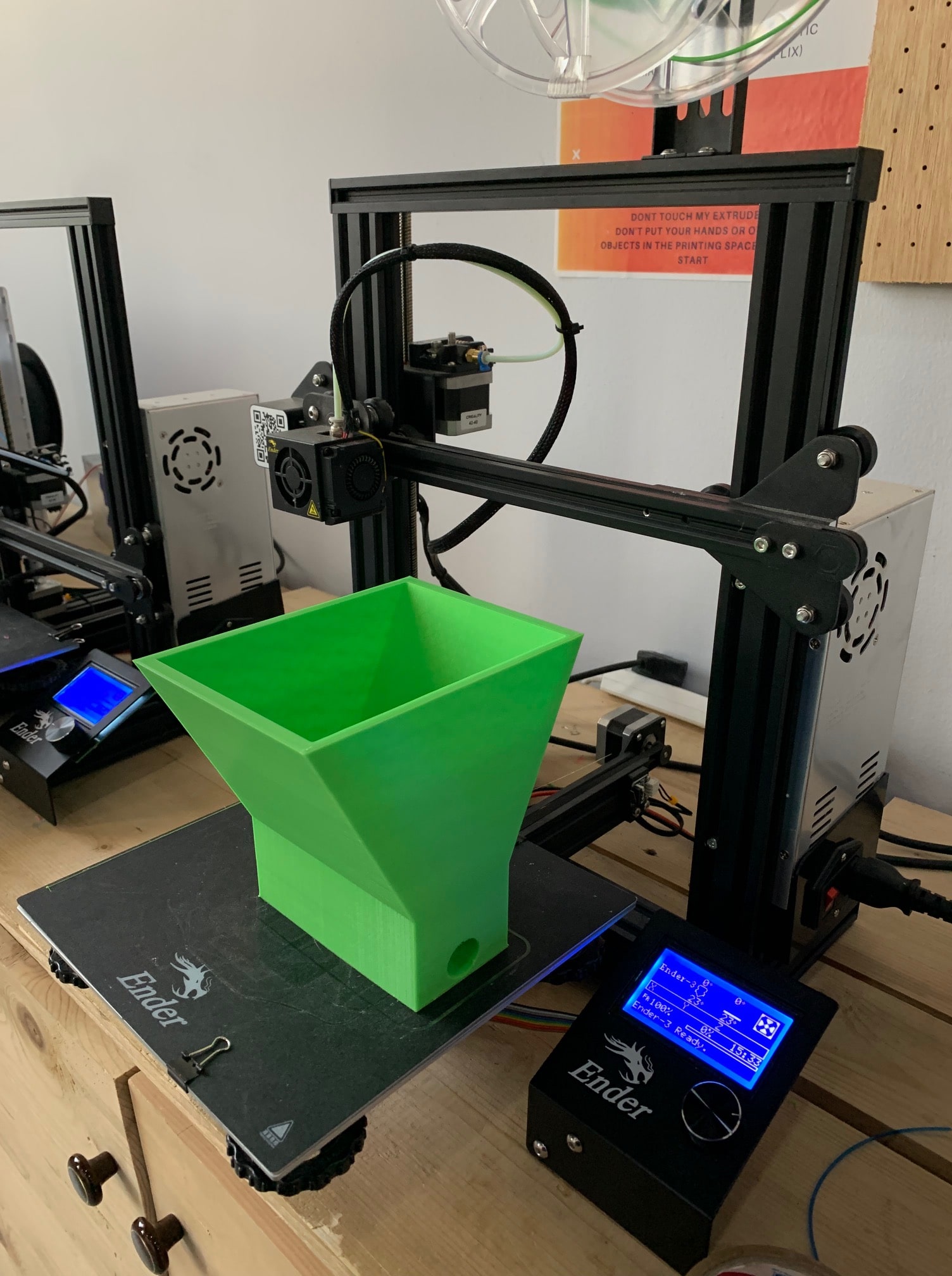
The hopper made with 3D printing, the design is made with FUSION360. Then transformed to CURA. We have firstly developed a design which did not worked perfectly because we did not take into consideration some of the dimension sized. The design of the hopper is taken from thingiverse website with the following link
Then I have scaled down the design to the desired dimensions.
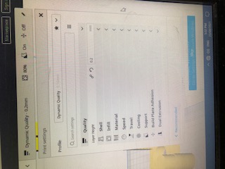
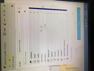
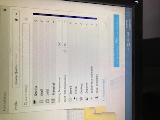
And thus the following photo is the 3d printed part I have followed these settings to perform the operation of printing. After slicing it on CURA it shows that it will take 15 hours to complete. I adjusted some parameters, to achieve high quality. I made the layer height 0.2 mm, the infill density 80% and the pattern “lines”, I chose the support to be at the bottom only at angle of 45 degrees, and the print speed 50 mm/s
The duration of the printing process was supposed to be approximately 1 day and 15 hours, which was acceptable, considering the result should be of high quality. I left it to print around 6:30 pm. I came to check on it the following morning, it turns out the filament broke, and my instructor stopped the machine. I fixed the filament issue and continued the printing process. I went to check on it again, after a couple of hours, the board moved, so the layers of the filament were not stacked on top of each other. And the following photo shows the results of the printing. I have printed my parts with some other parts that is explains the printing time is long.
And this is the final results.
Attempt02
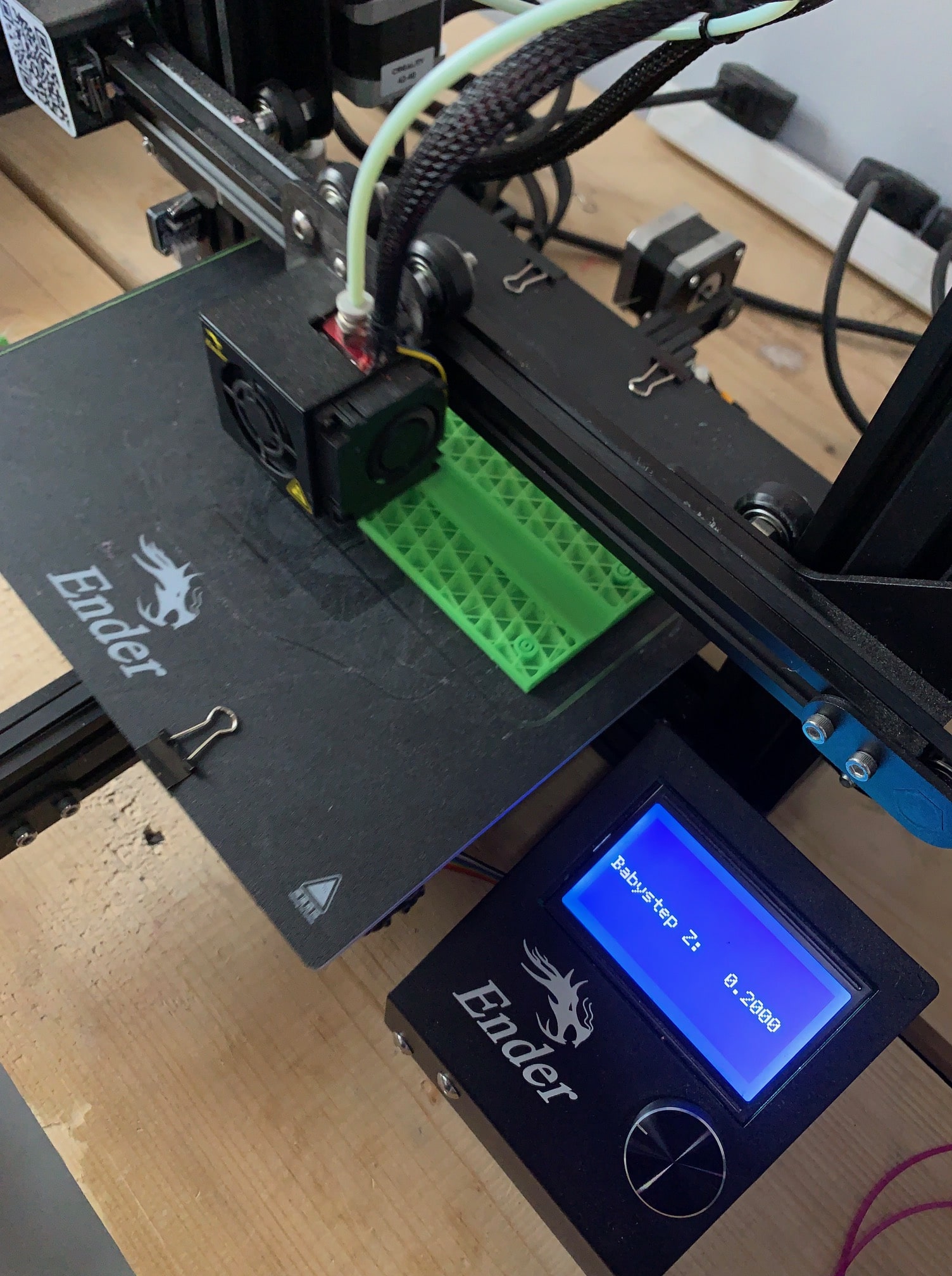
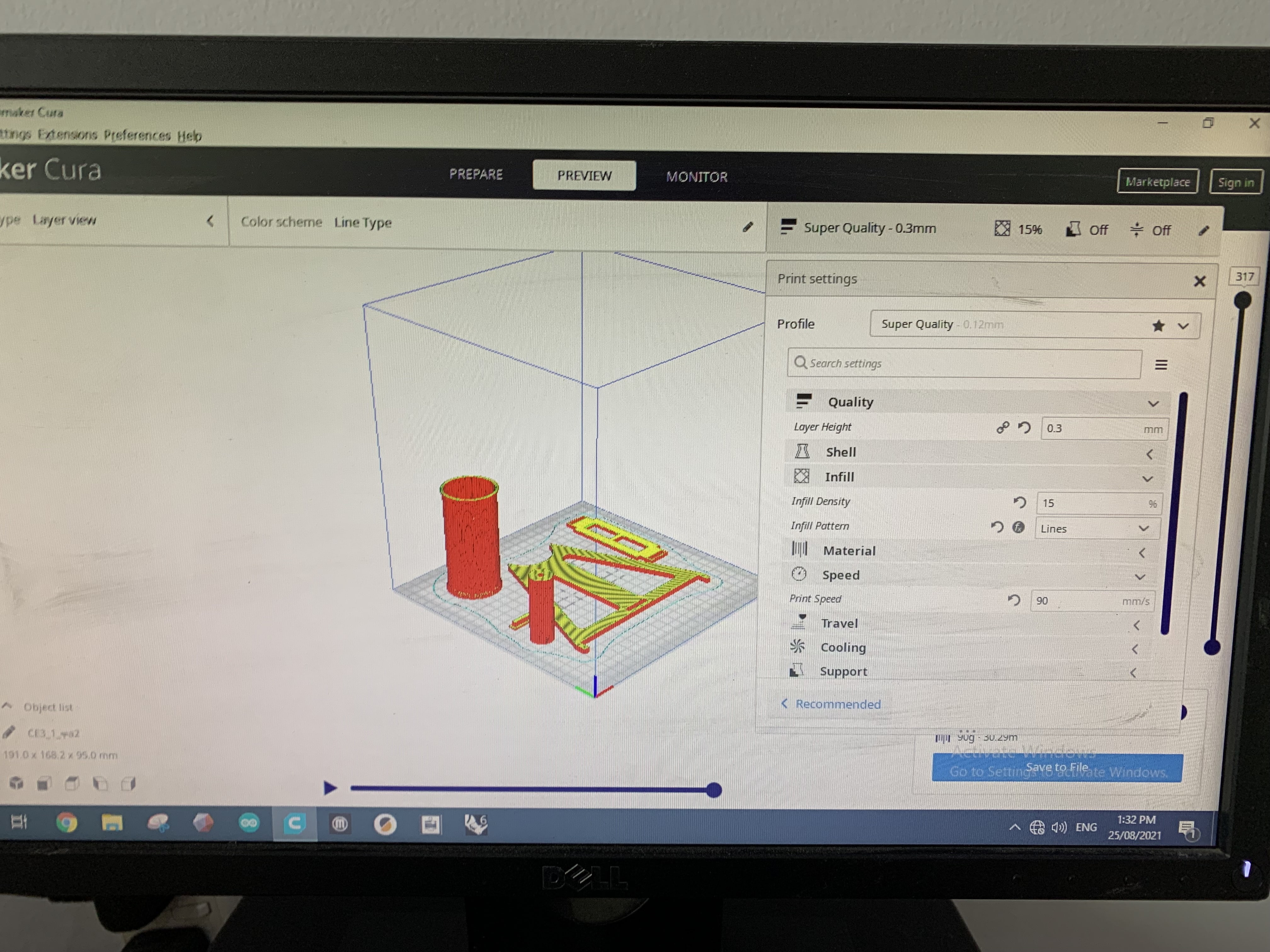
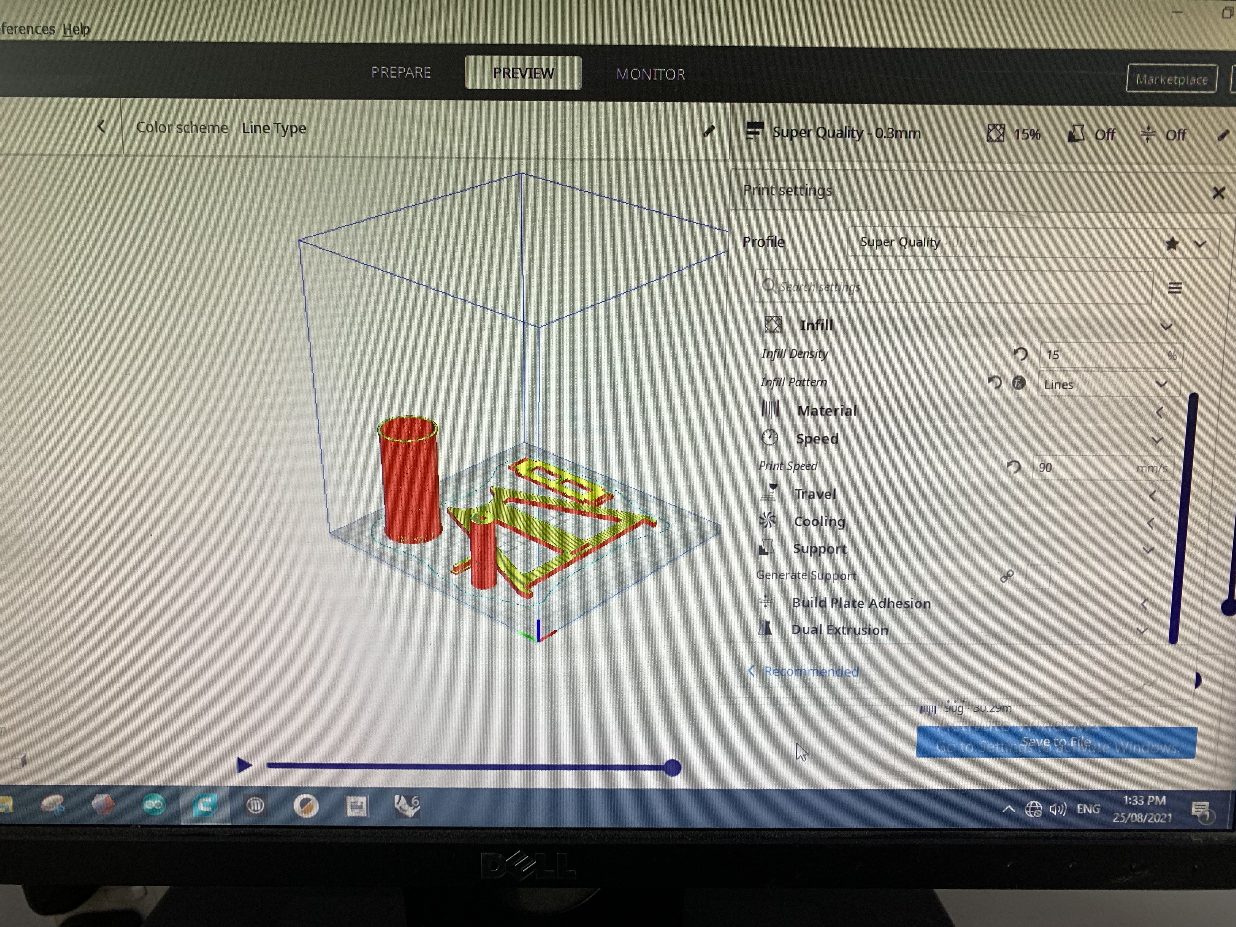
I have decided to do it again my two pieces of printing ere together with the following settings.
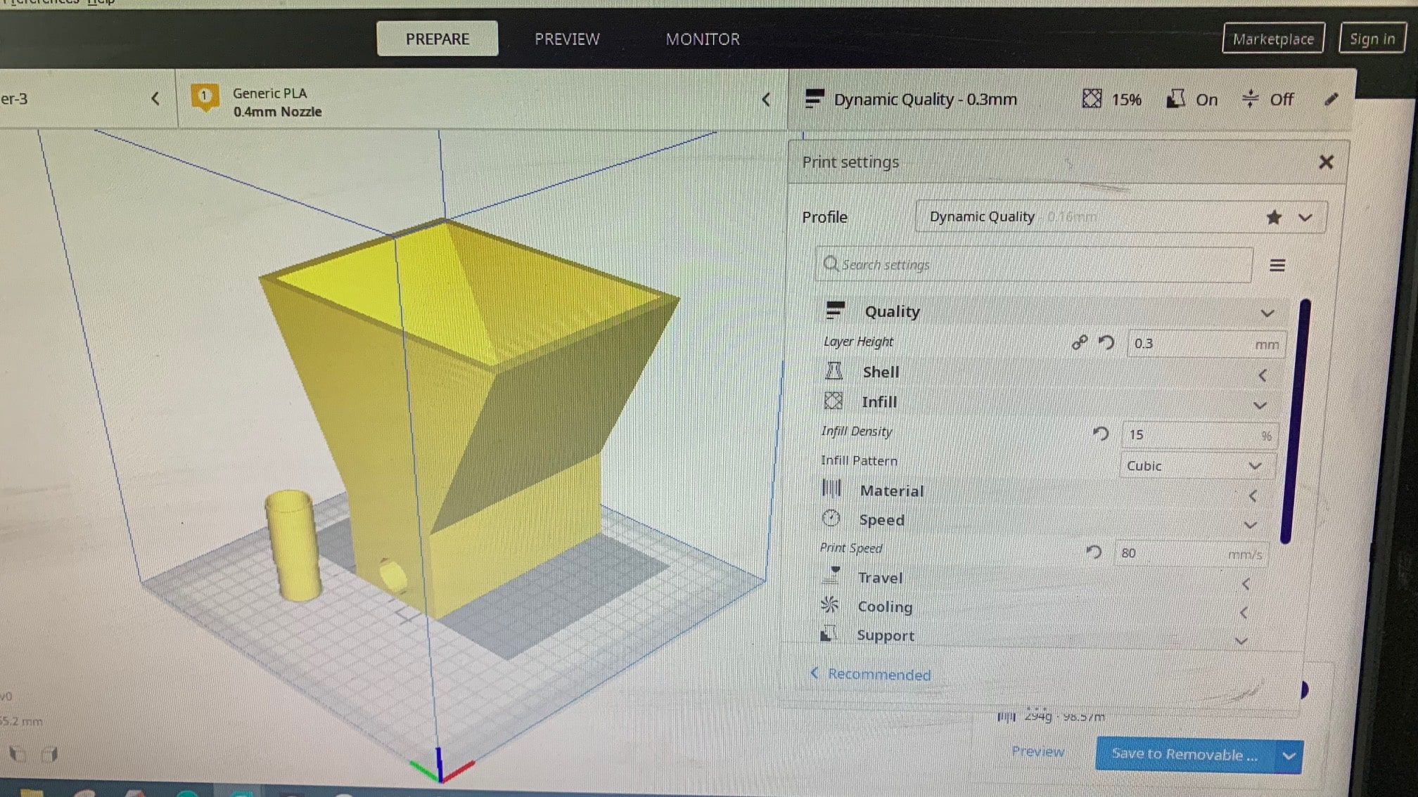
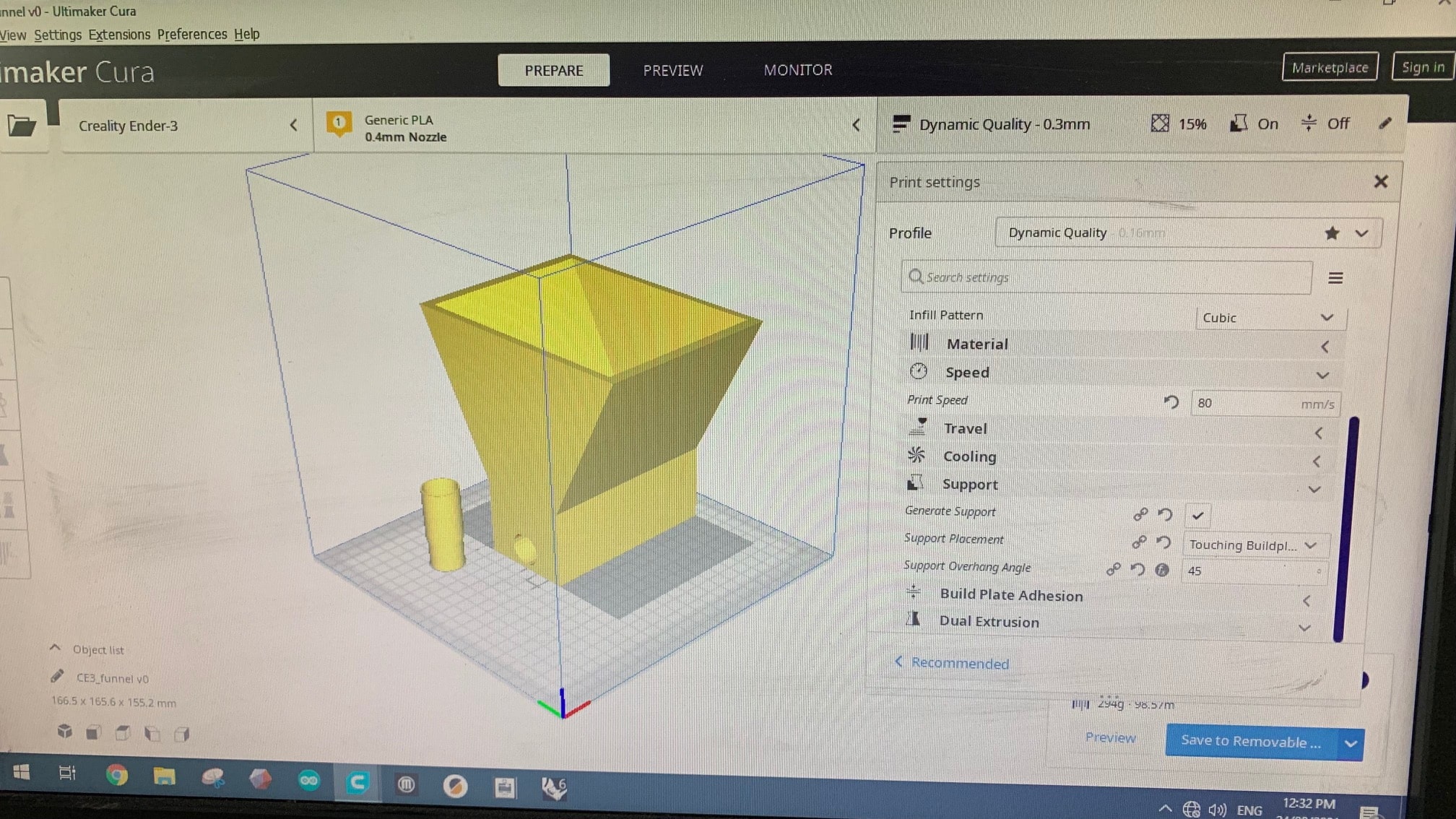
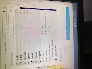
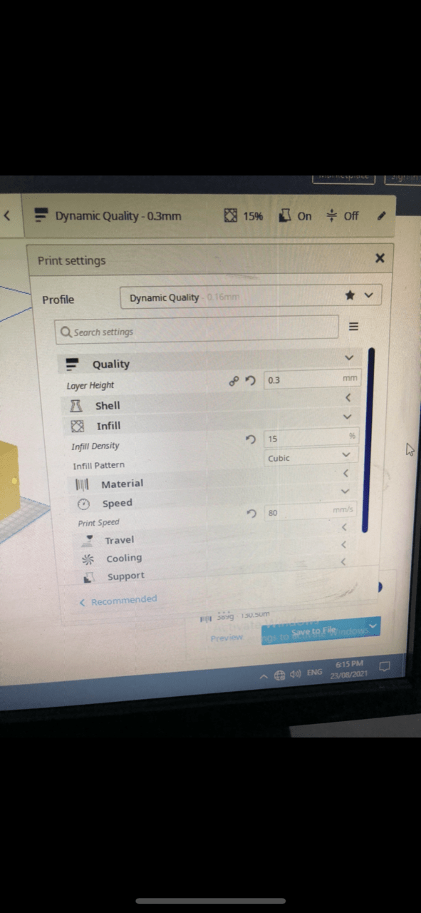
The layer height is the same as the first which is 0.3mm. The infill density is also the same with 15%, and the pattern is cubic. The printing speed has increased to 80 mm/s from 50 mm/s to reduce the printing time. and the Support is applied on the 45 degrees.
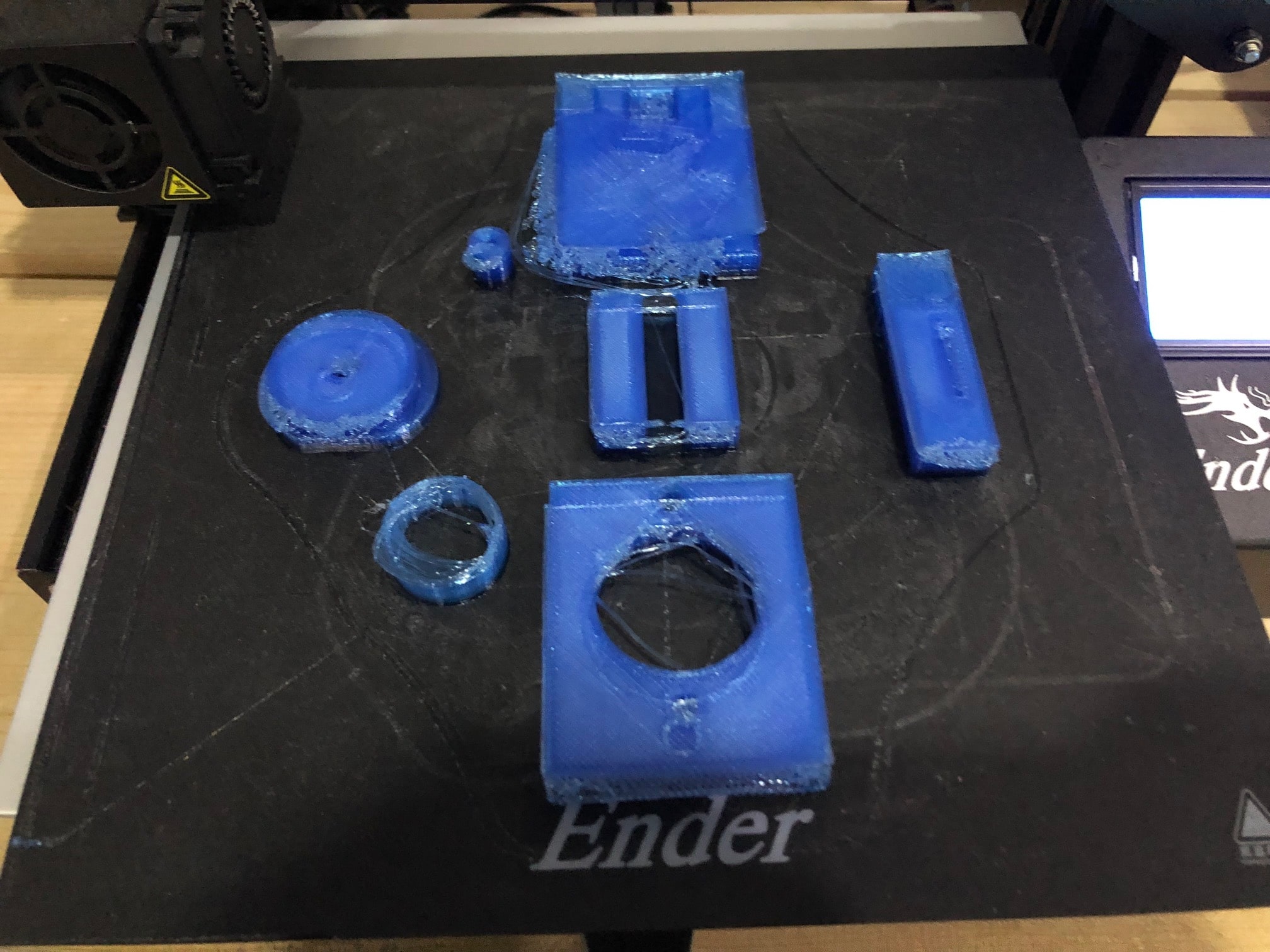
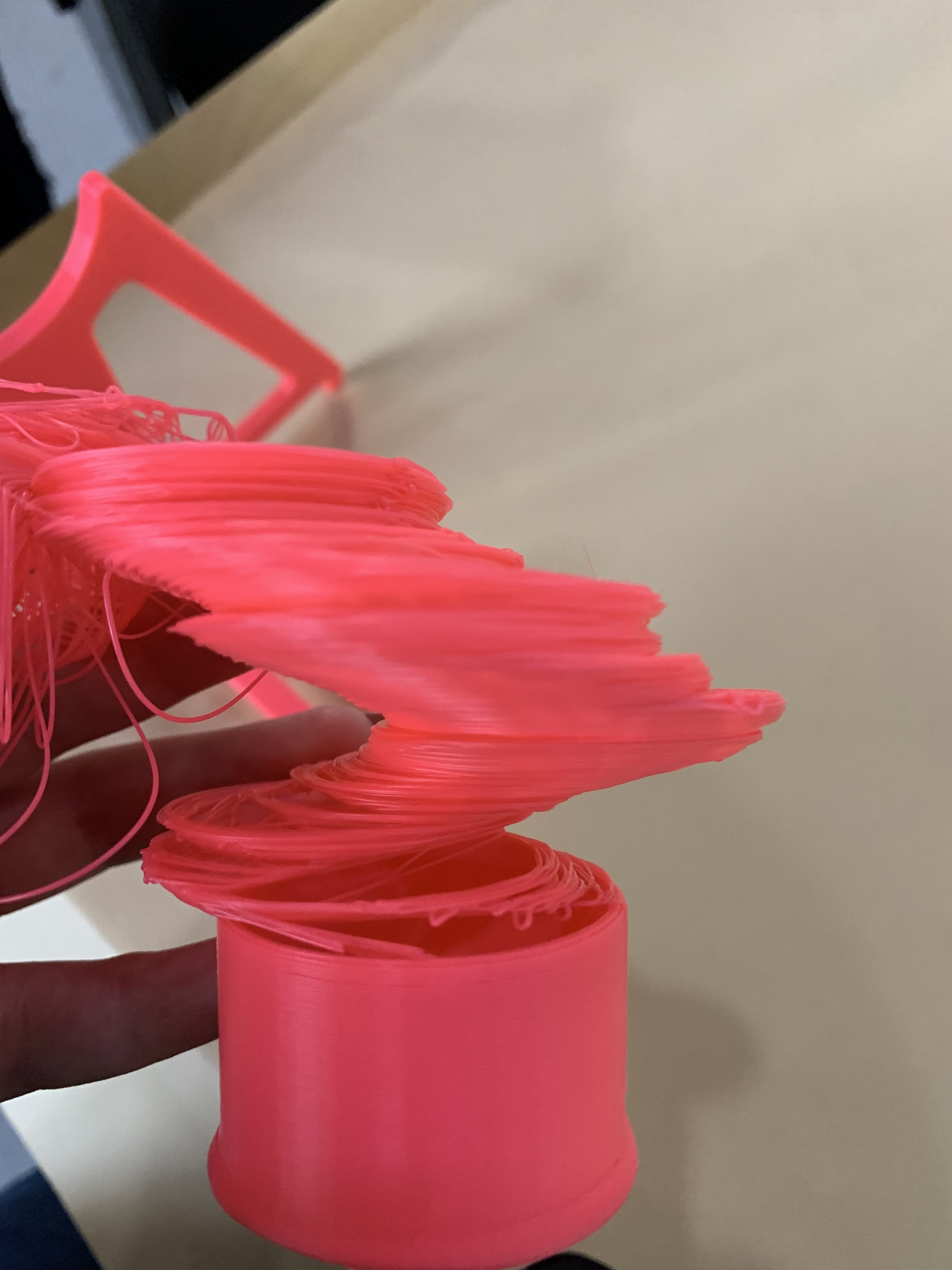
The results after printing took 15 hours, and the baby step that I have done to the printer is 0.2mm.
Attempt03
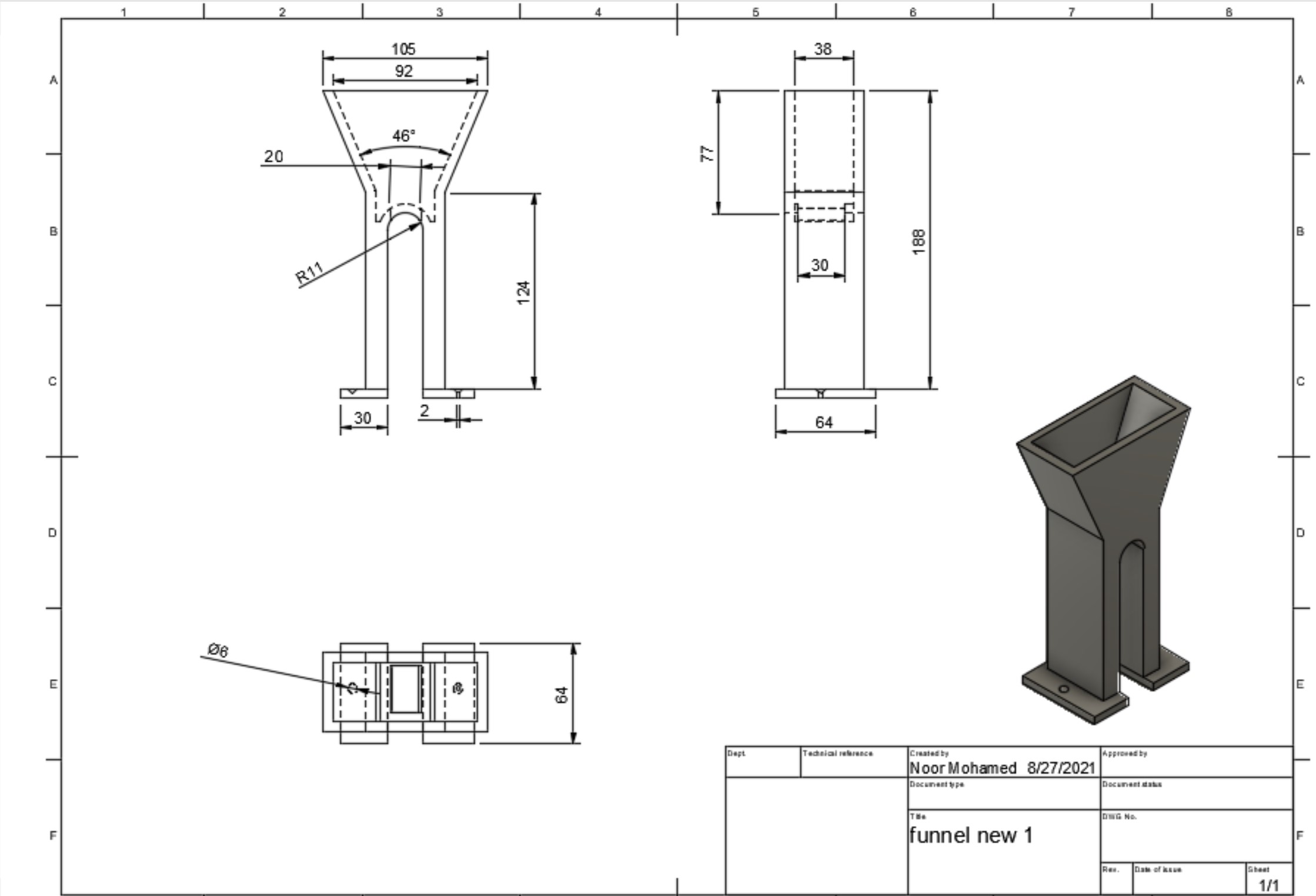
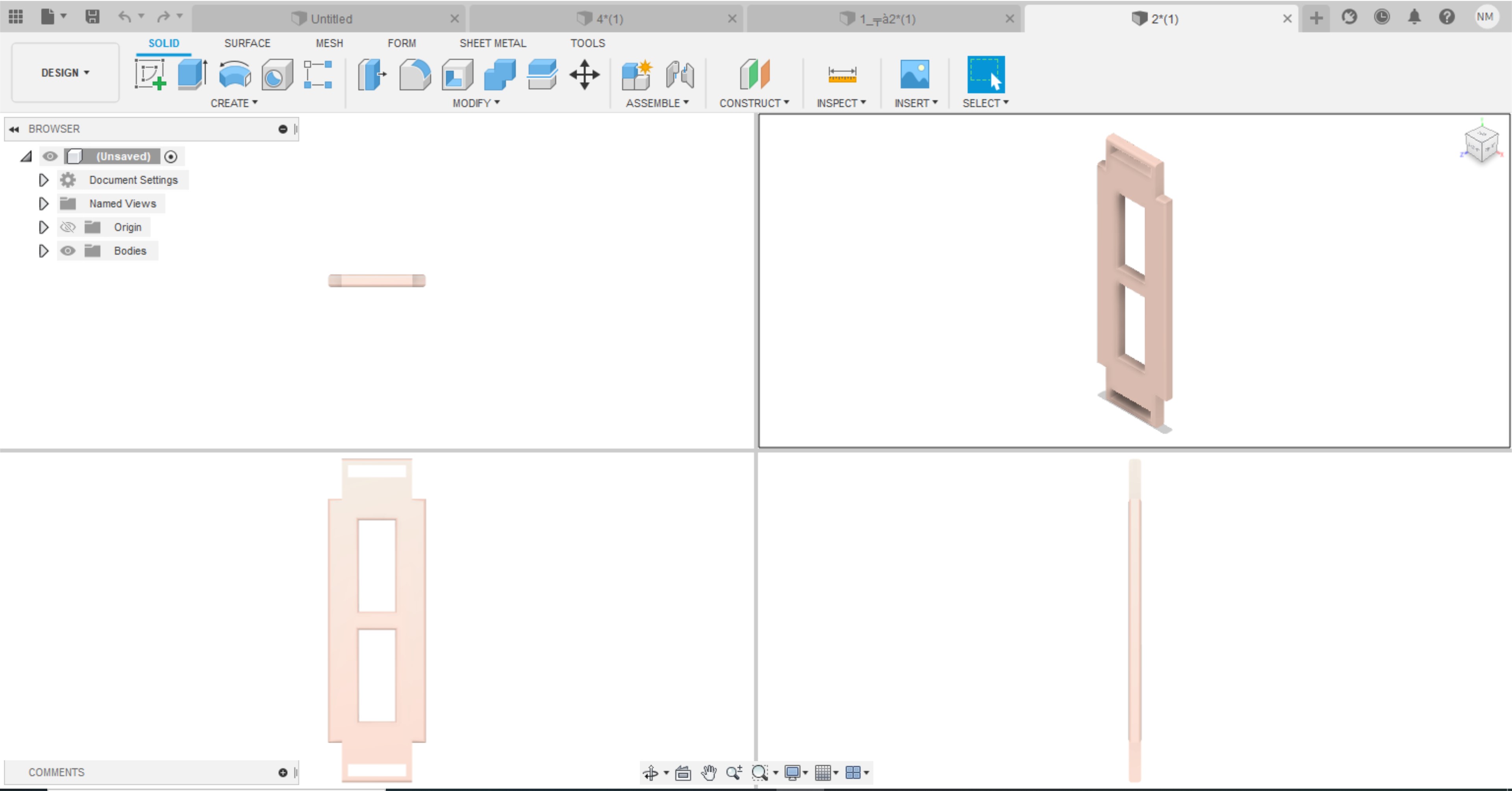
The second design made is different, for some of our desired specifications. The following video show the design of the hopper.
The following photo shows the technical drawing
I have followed other settings shown below to perform the operation
And, final result is in the following photo

Coupler Design
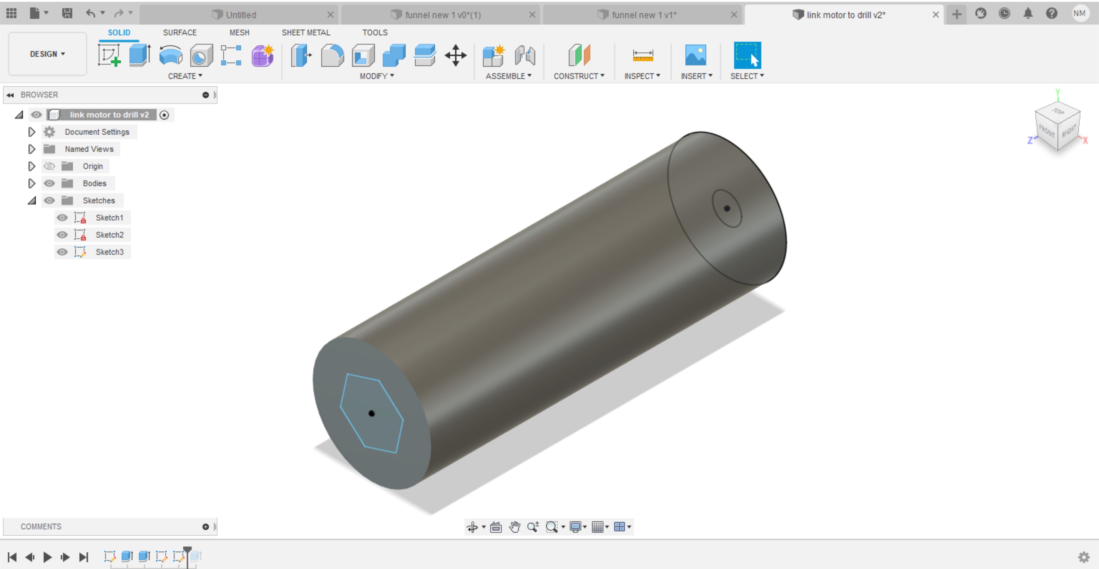
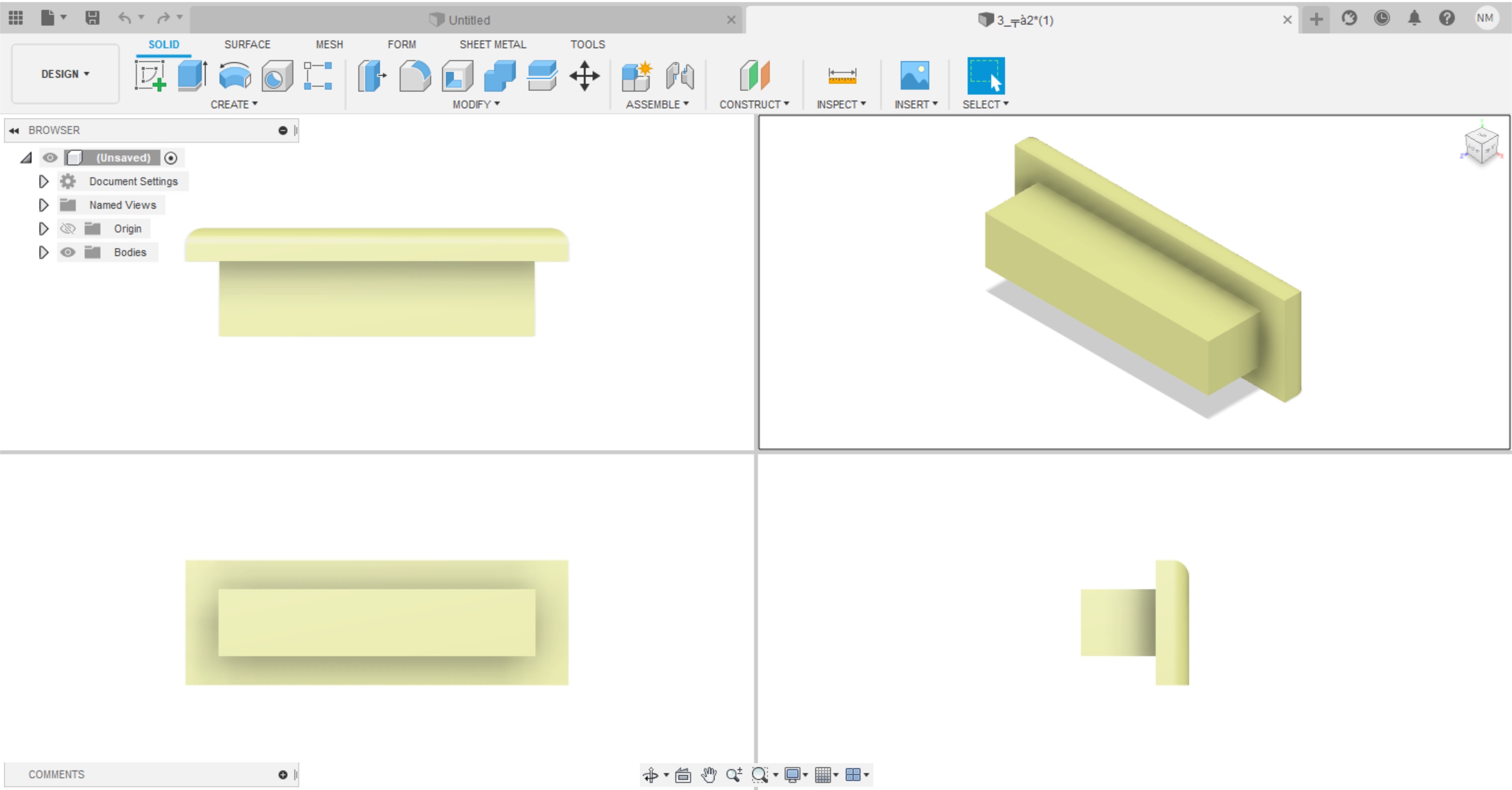
The coupler as we stated in the background section will connect the motor to the drill bit, there is no specific design to the couplers used in the industry. I made a design to print in FUSION360 as you I will be listed on the following pictures.
I have made the elementary skitch of the coupler link as shown in the following photo.
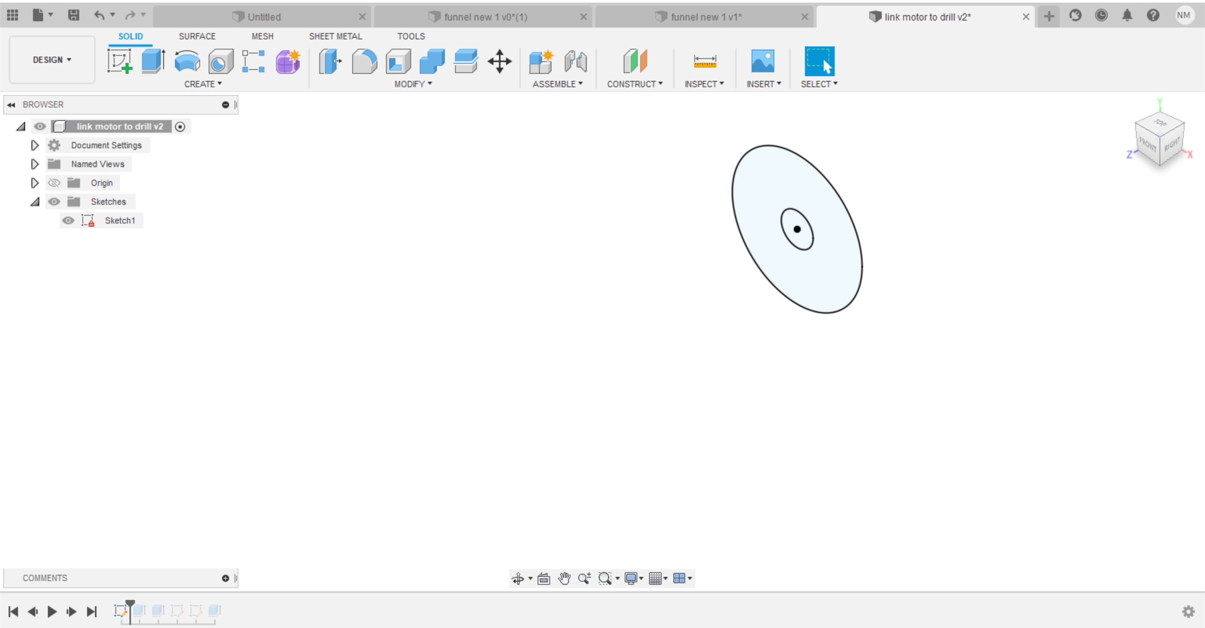
Then extrude the sketch to the desired dimensions I have extruded to 60mm.
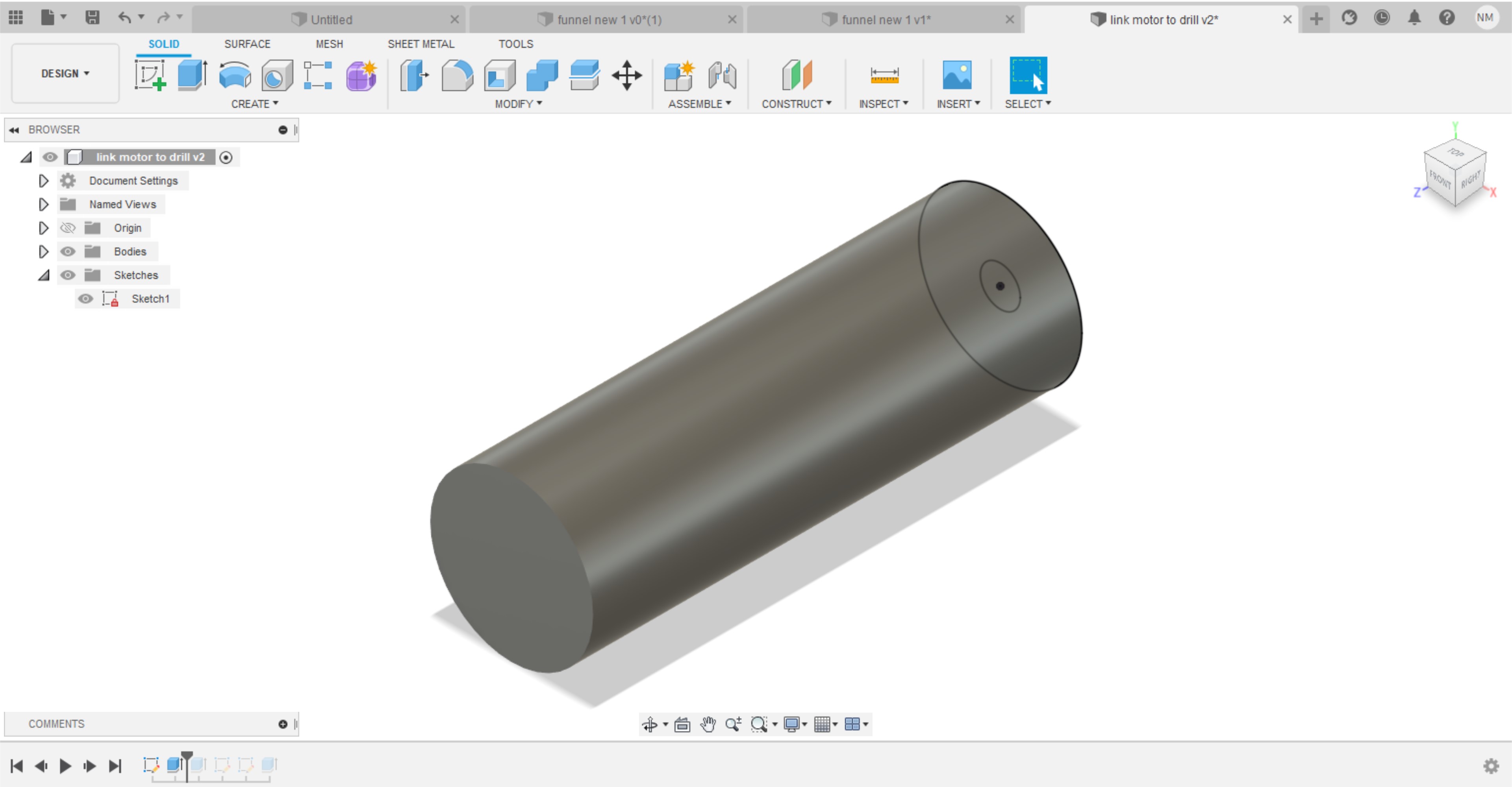
Then done a hole extrusion to the inner circle drawn in the skitch with the following extrusion cut of 20mm.
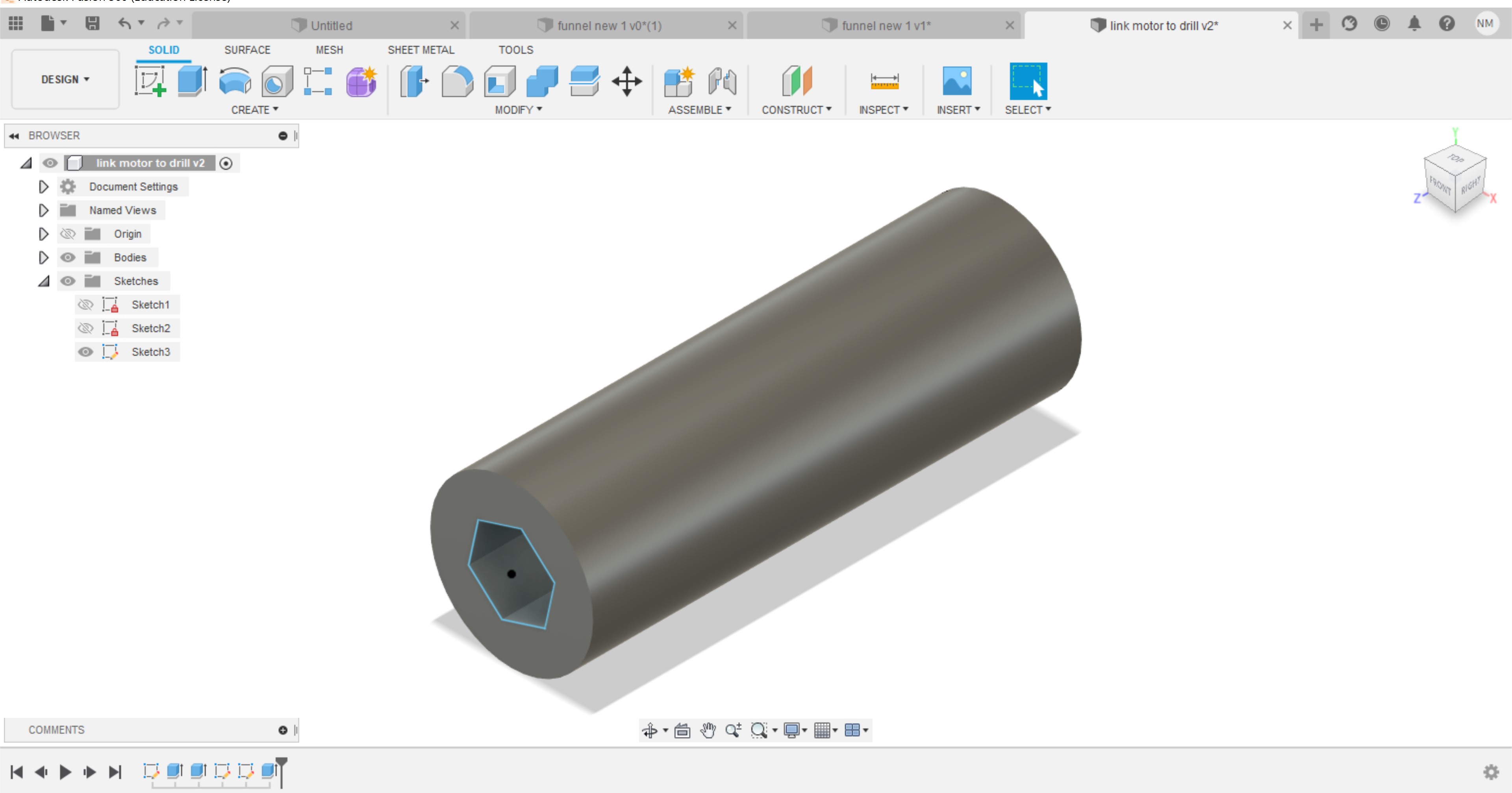
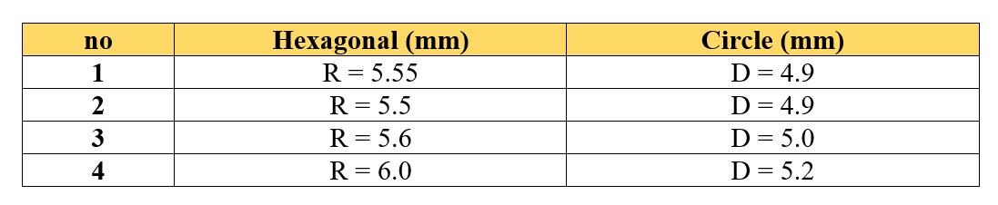
Drawn another sketch to the other side of the link with a hexagonal shape to the entry of the drill bit holder section after measuring the diameter of the drill bit to make sue it is slightly fit. The fitting should not be necessary extremely fitted. the diameter is 11mm.
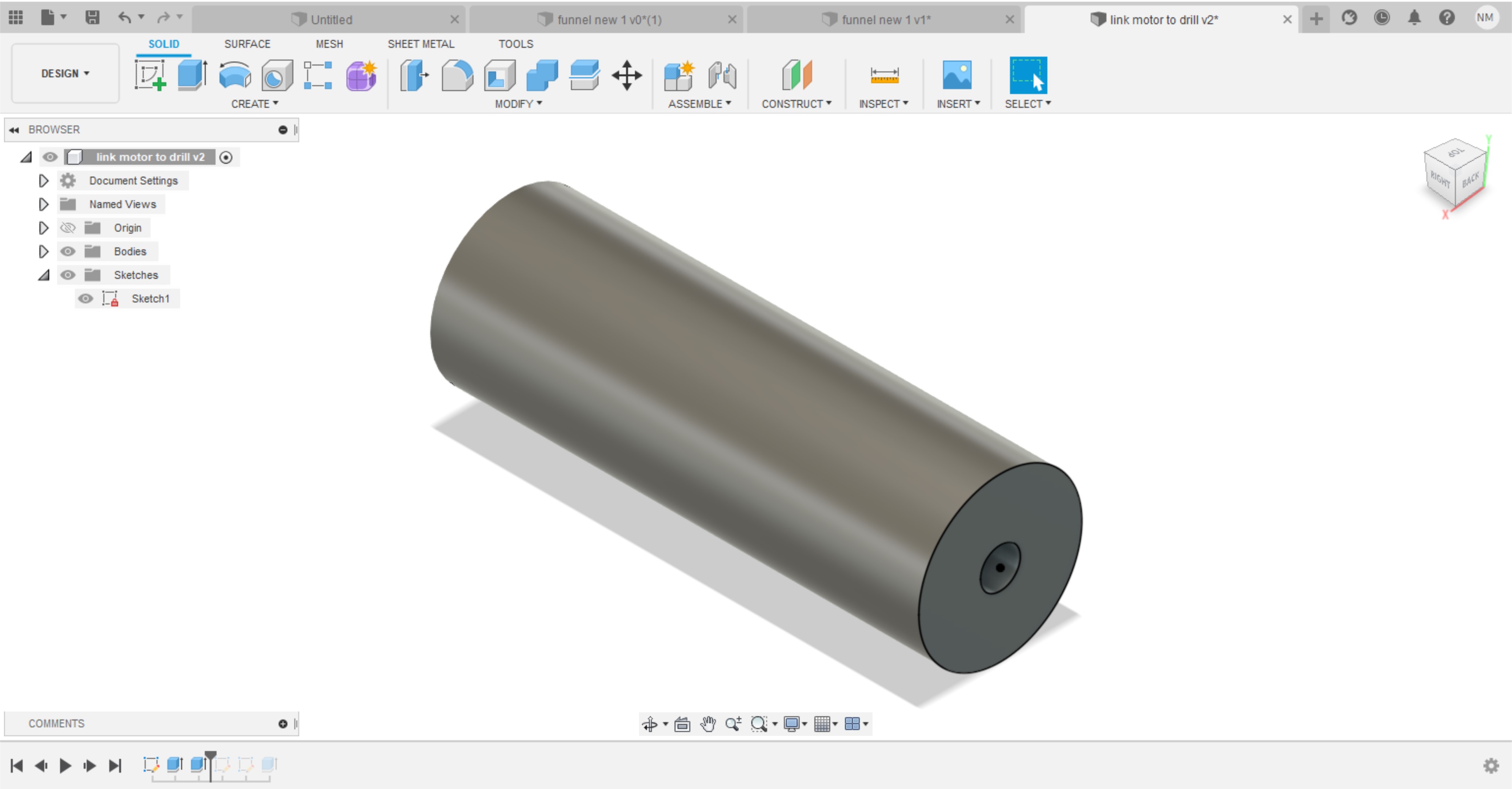
Then extrude cut the hole to the desired place I have chose it to be randomly 20mm
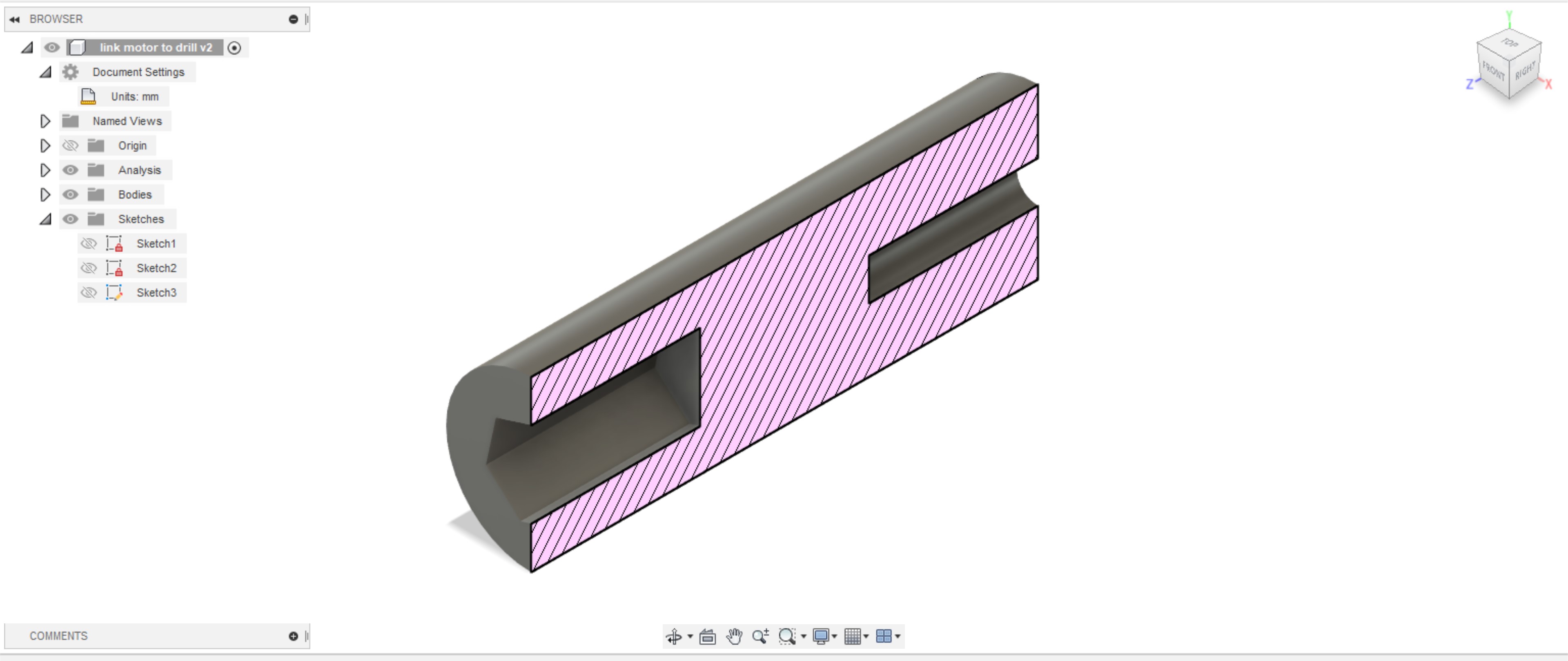
And the following photo shows the section analysis view to have a better understanding of the holes inside the coupler.
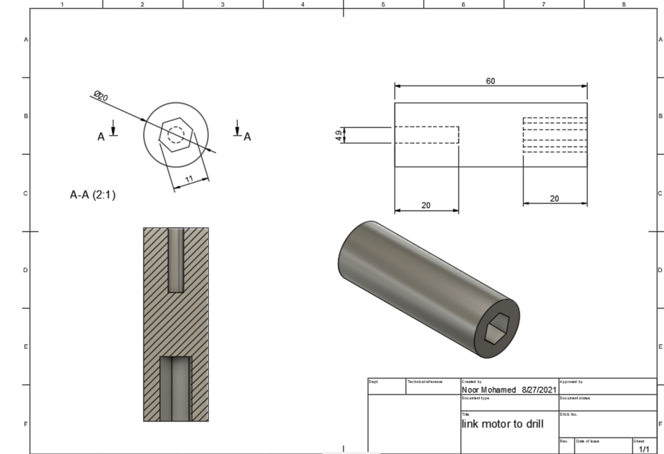
The following drawing is the technical drawing of the design
The following picture shows the printed designs I have made. Some of them worked and the other did not. The settings applied is stated in the following designed 3d project printed. I printed the design with the hopper, and other designs settings. The settings worked for the hopper was the best so I have used them.
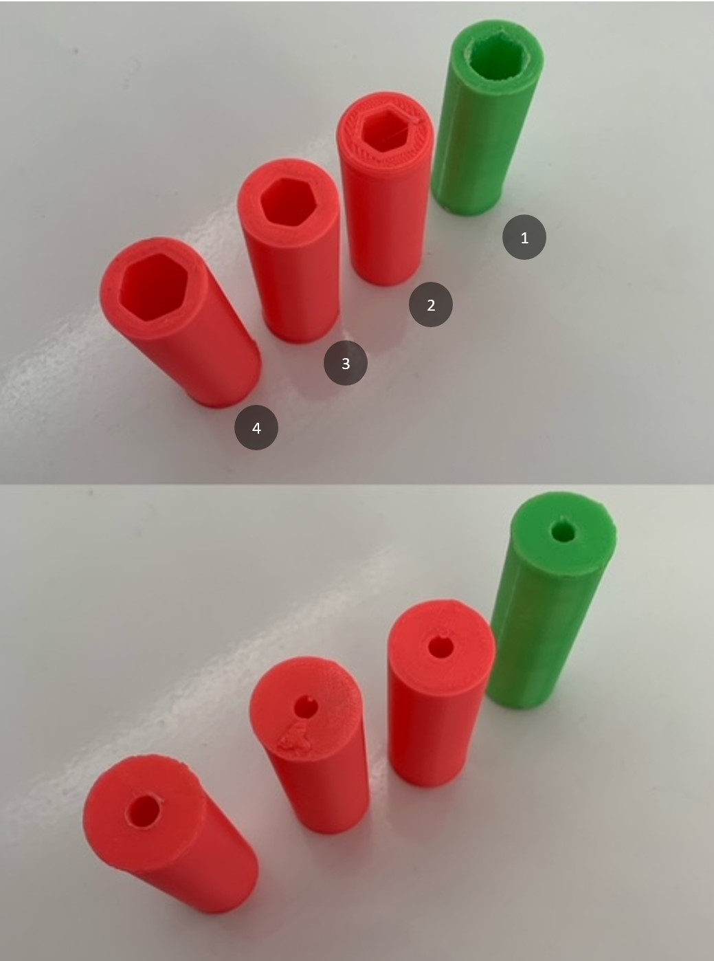
And the following table shows the dimensions of the above pieces printed.
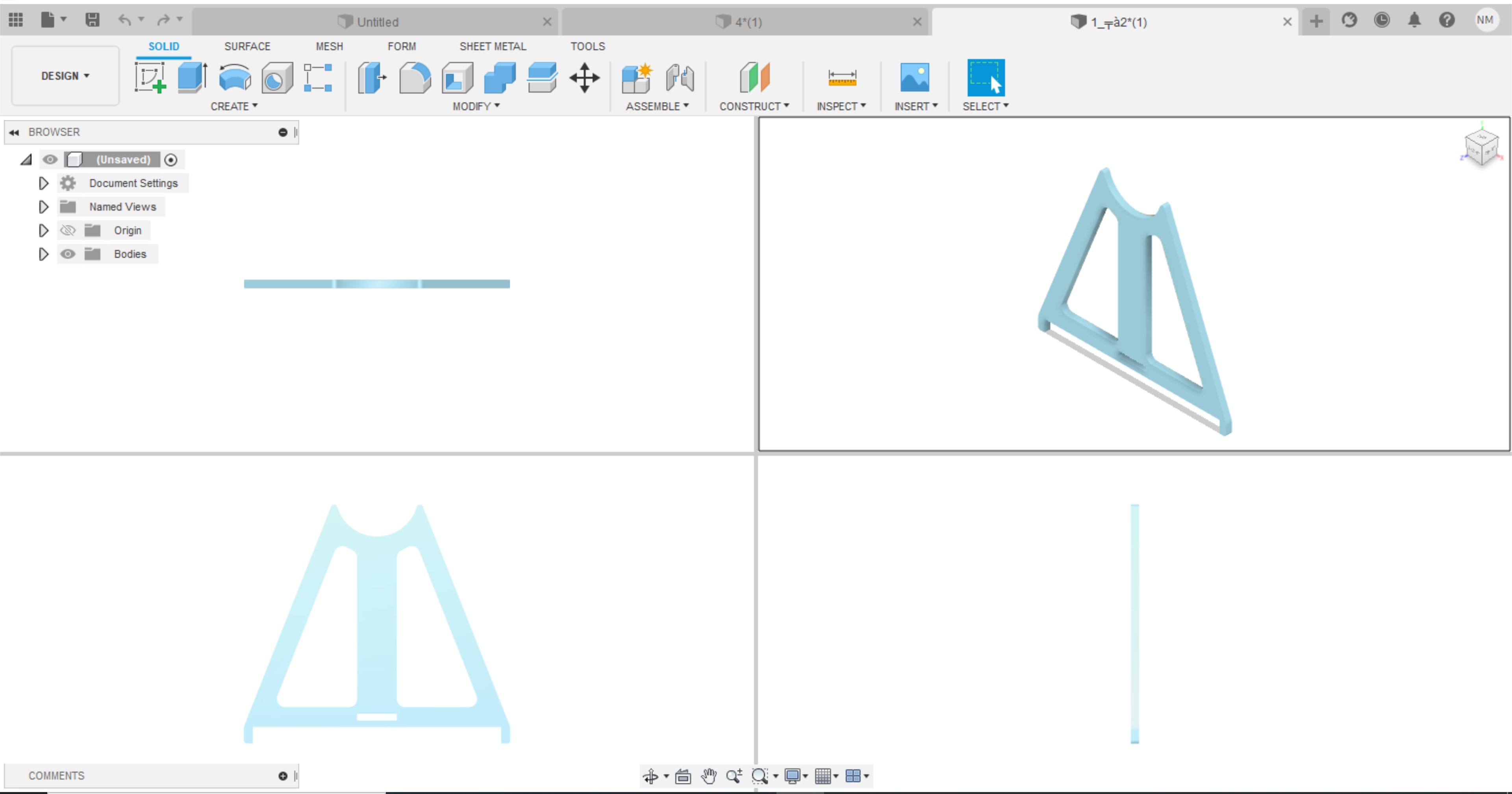
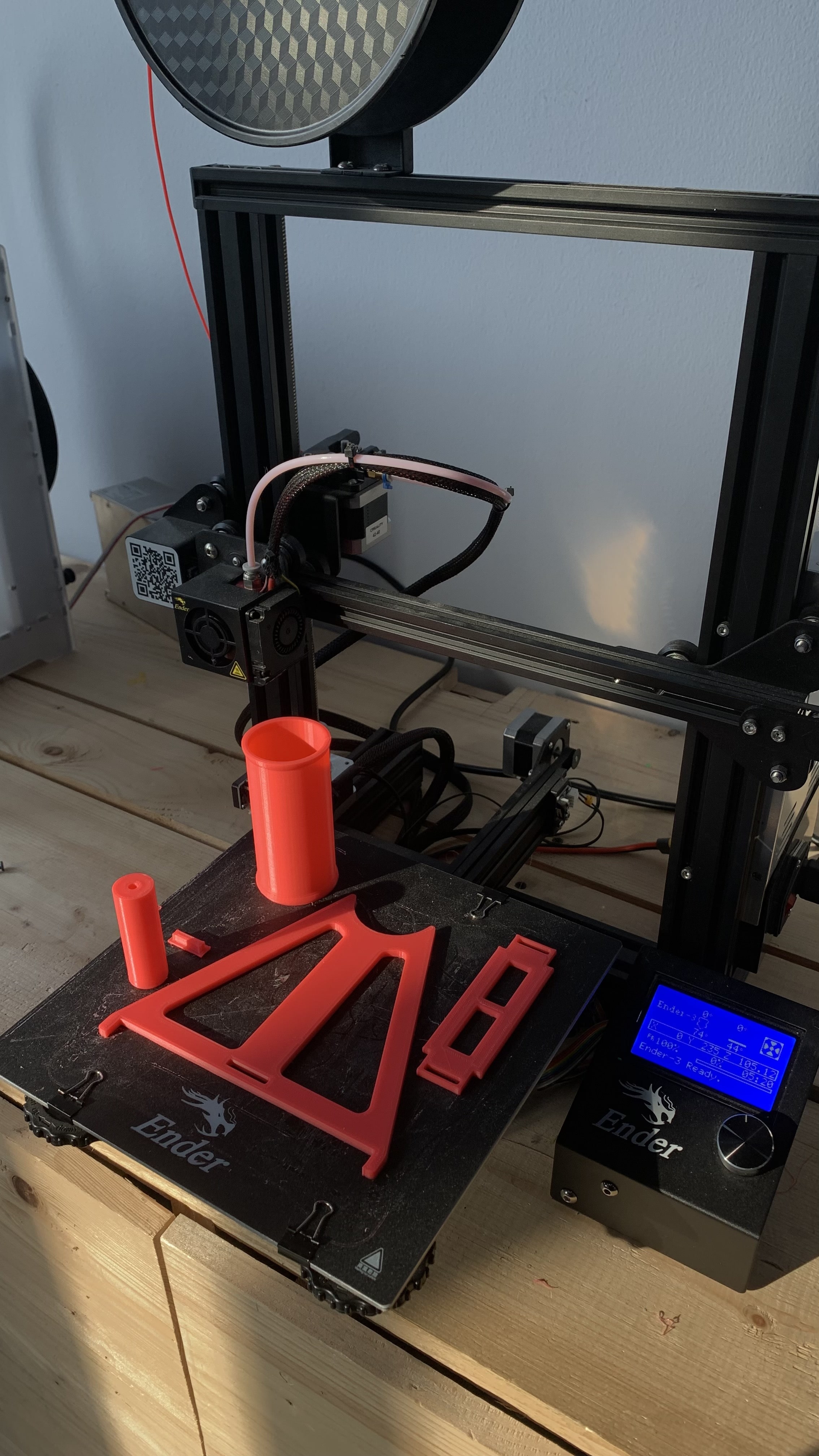
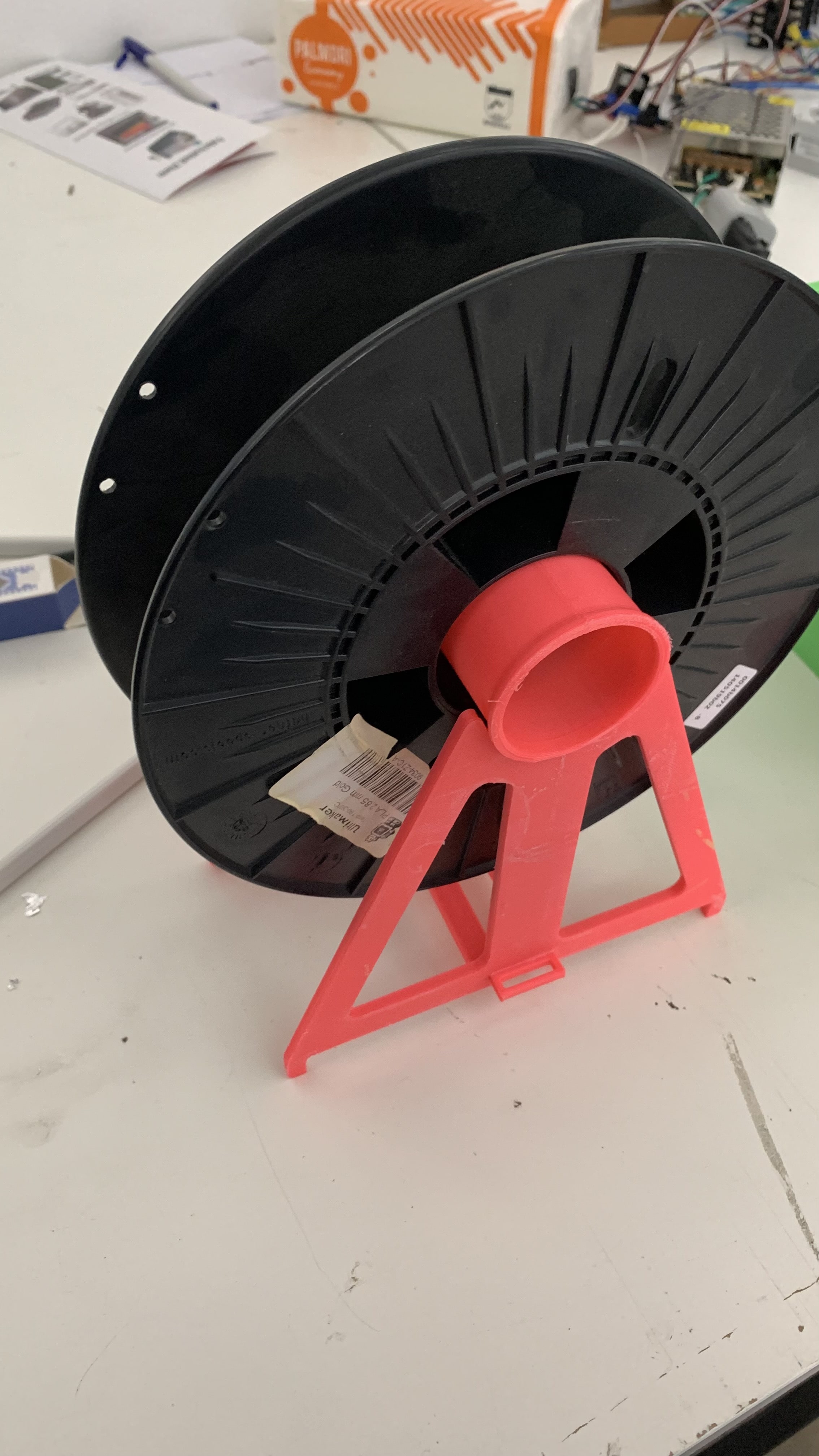
Spool Holder
We have designed a spool holder to put the extruded filaments on the spool. The designed is taken from thingiverse and printed using the 3d printer machine.
The first piece is the link piece were when you assemble the spool holder it locks the frame together
The second piece is the structure holder, were you should have 2 of them in the structure. As two legs.
The link that should connect the two legs is shown in the following photo.
Attempt01
I have printed the design on one of the settings provided above, but id did not print well. The board bed kept spinning and ruined the cylindrical shape piece as you can see in the following photo.
But the other pieces went well. I have printed one structure holder (or leg), and the base of the structure and one of the links that hold the structure together.
Attempt02
I performed the same settings in the first attempt and changed the baby step to the machine to -4.9mm. Hence, the printed parts is listed in the below pictures. It took 5 hours to print the design.
And this is after attaching all the pieces together, I did not use the link holder, because it was not necessary to put.
Heat Element Design
In our project we need a heater to heat the materials inside the pipe to larger than 220 degree. So to put a heater and control it we need some parts like heater,
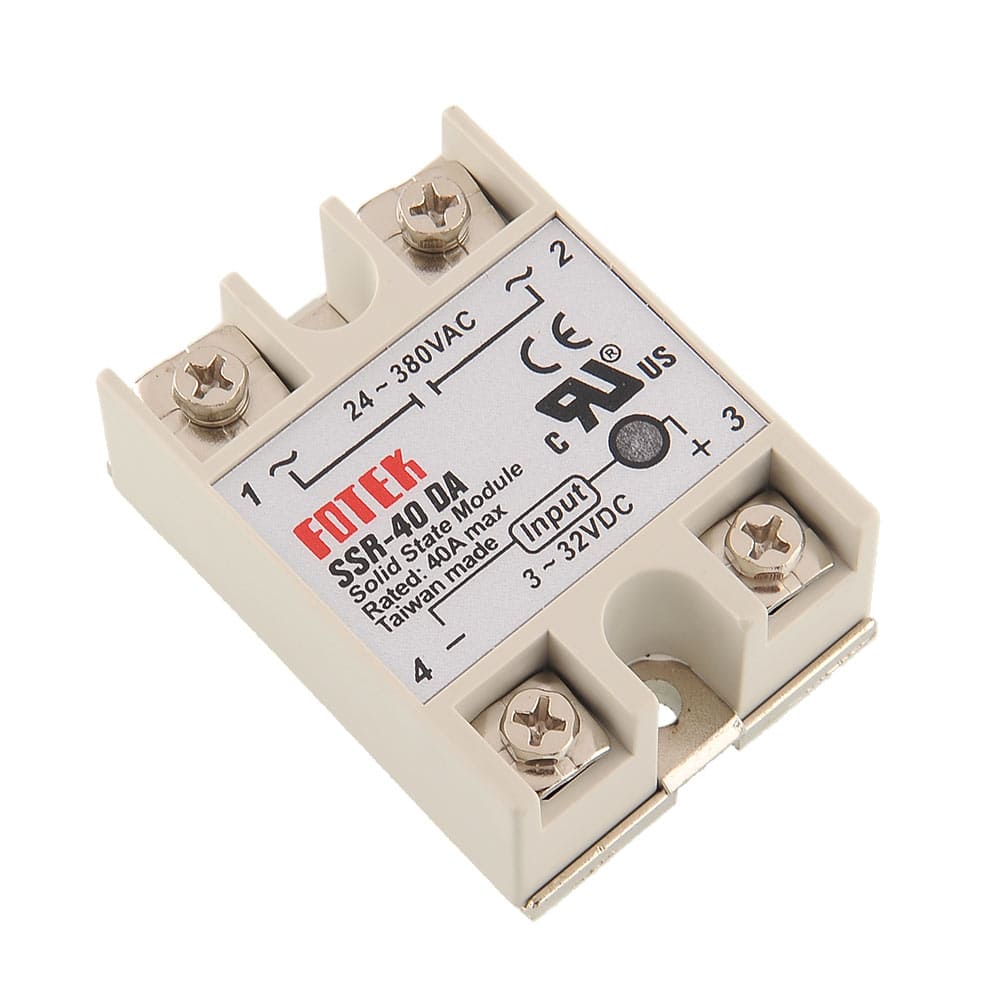
SSR-40 DA solid state or sensor temperature
datasheet of SSR-40 DA solid state relay
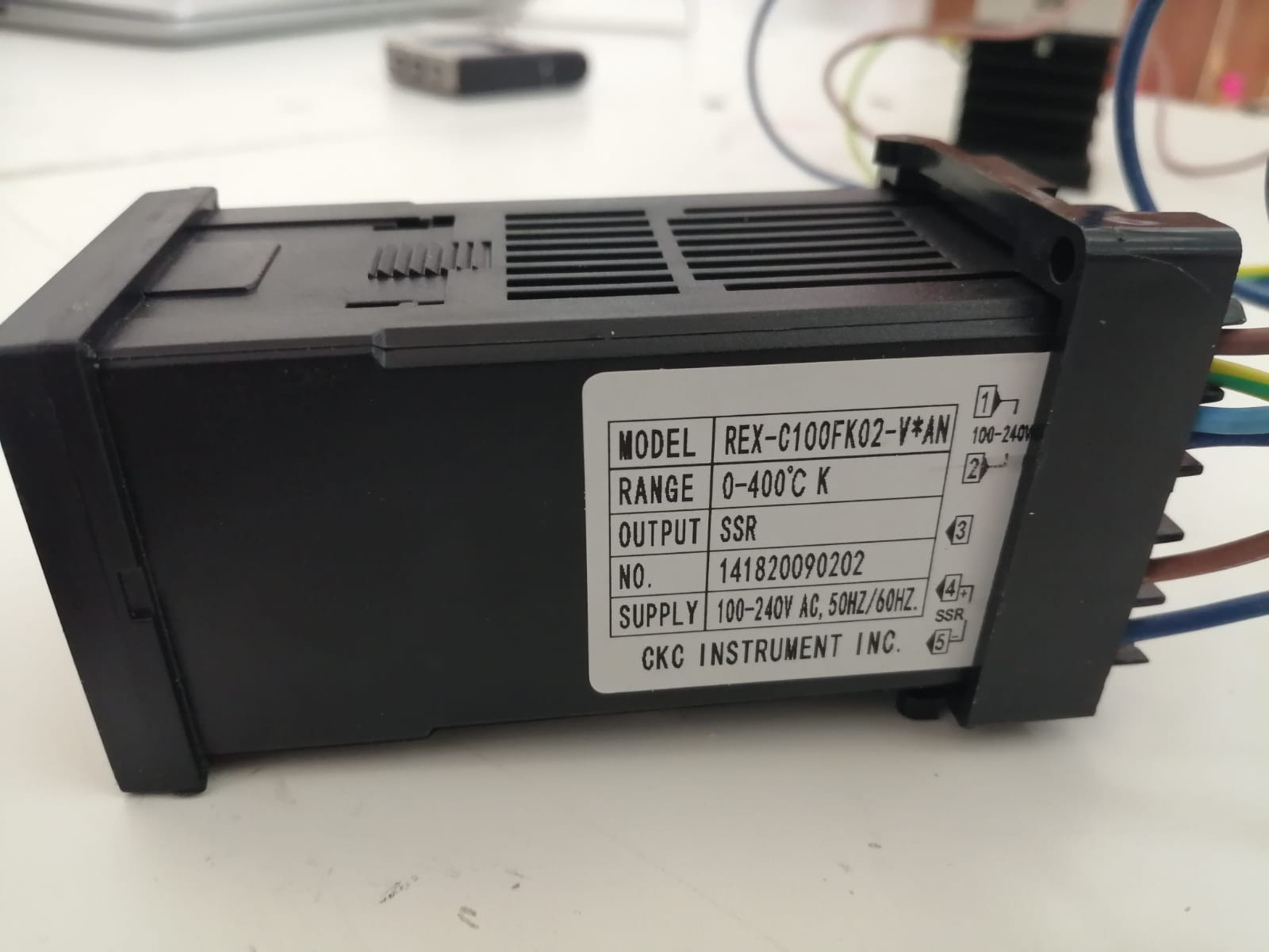
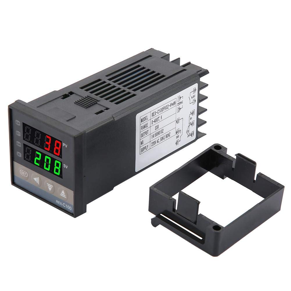
and Digital Temperature Controller REX-C100FK02-V×an.
datasheet of REX-C100FK02-V×an
We should connect them together using wires and they will look like this after finish the connection.
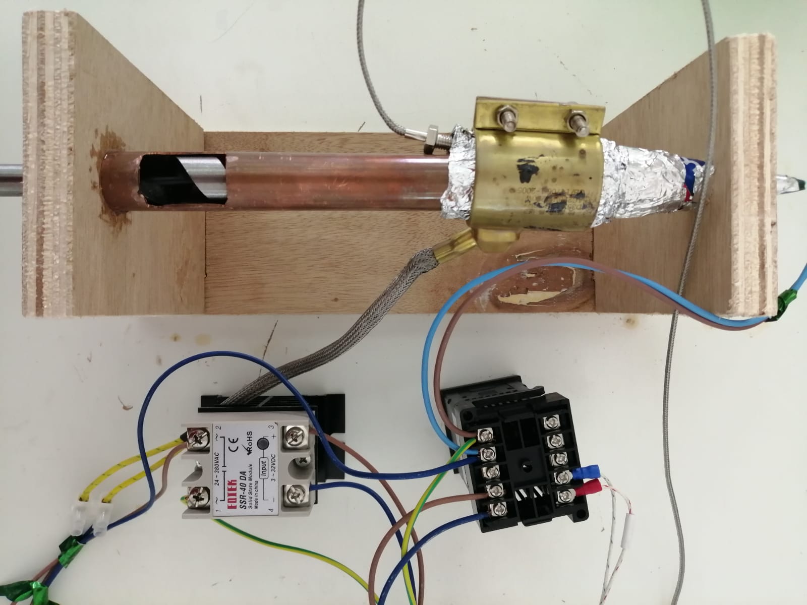 And this is another picture show us where the wires linked to any pins.
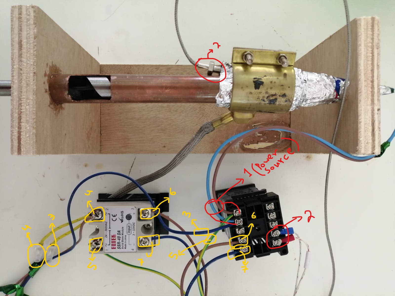
Number one are two wires connected with the power source to give Digital Temperature Controller power that control it and give it also to the heater. Number two are two wires that come from the thermocouple that measure the temperature degree. Number three is a wire come from heater and connected with the blue wire that come from the power source at Digital Temperature Controller. Number four is also another wire come from the heater and connected with pin 2 at the SSR-40 DA solid state. Number five is a green wire that connected with the brouwn wire that come from the power source at the Digital Temperature Controller with the pin 1 at the SSR-40 DA solid state to give it power. Number six is a wire connect between Digital Temperature Controller with the pin 3 at the SSR-40 DA solid state. Number seven is a wire connect between Digital Temperature Controller with the pin 4 at the SSR-40 DA solid state. And this part work by give it a power and from the Digital Temperature Controller you can change the required temperature and it will give the heater the needed power to reach this temperature.
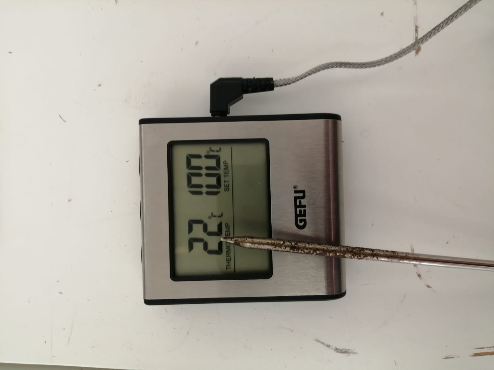 Finally, this is a thermometer that you should use it at the end to check if the showed temperature at the Digital Temperature Controller is true or not if it is not so you can conclude that there is something wrong with your part or connection.
Motor Design
Now we will talk about motor type how we design it or how we combination and link it with the project and what have we did to control it.
First, we need some part that we took it from the lab like mercury motor.
And S-60-12 or 60W single output switch supply is AC-DC Enclosed power supply; Output +12Vdc at 5A
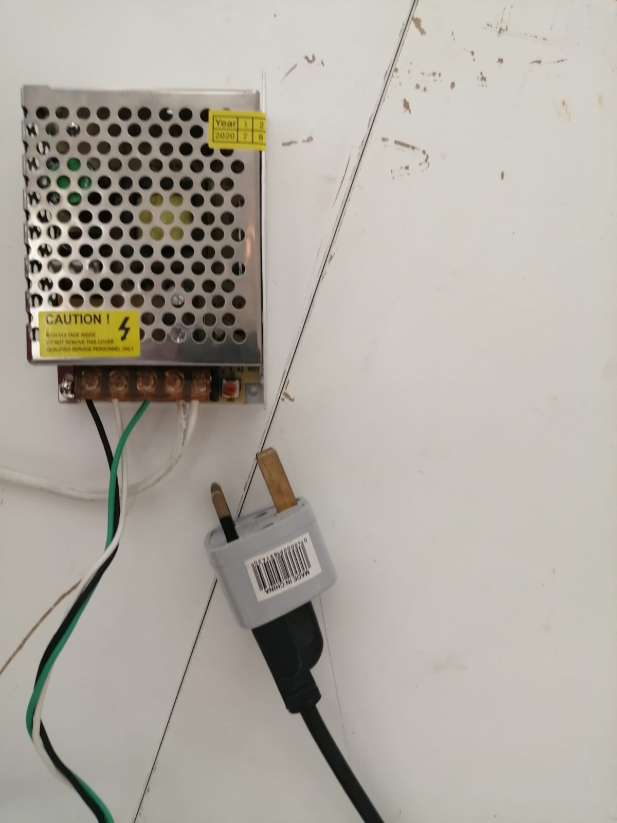
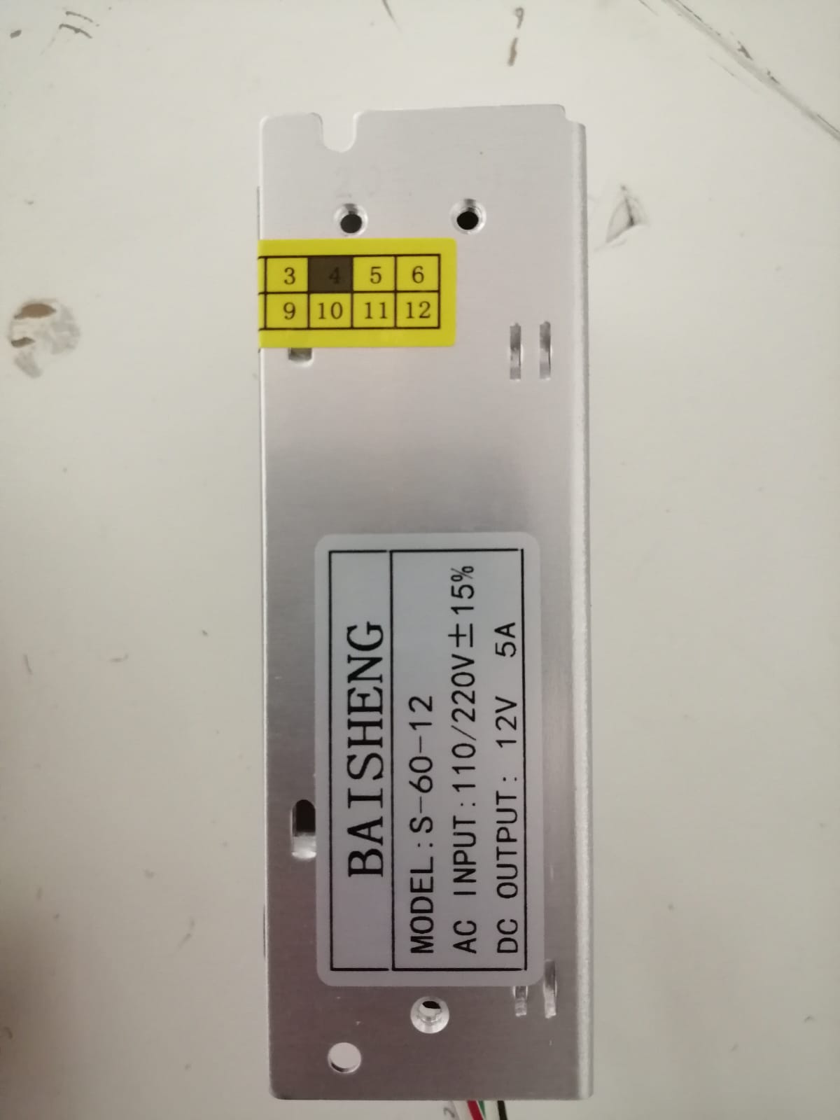 specification datasheet of 2-60-12 and quality Engineering test report from these two data you can see the specification of this part and quality of it based on some test.
And L298N or motor drive controller board
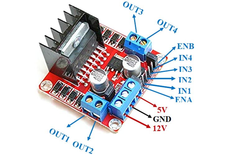 I took this picture from this website COMPONENTS101 that they put arrows on the pins to tell you or led you what to connect with it.
And Microcontroller that we use it to link the parts with the laptop and by using Arduino we can control RPM and rotation direction. And Bread board with jump wires
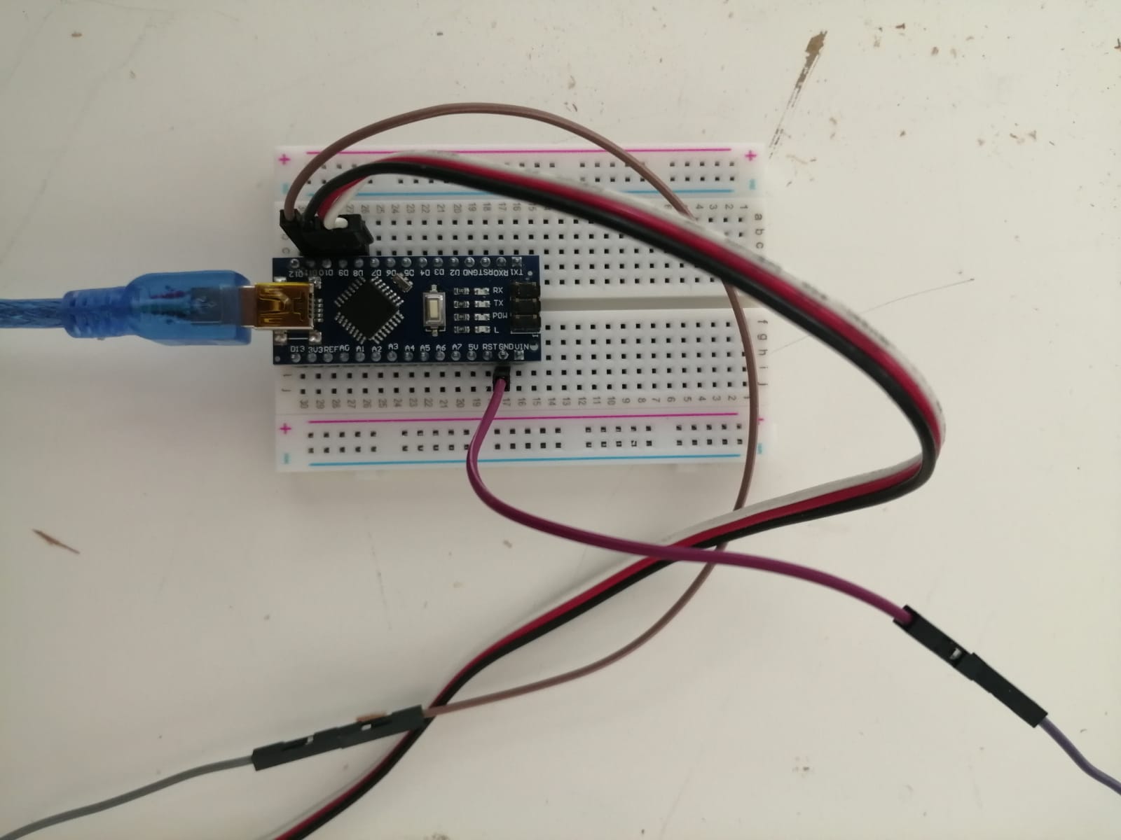
These are the part that we need it to make the drill pit spin and force the material inside the pipe and get out as filaments.
Second, we will talk about how we can combination or link these part together.
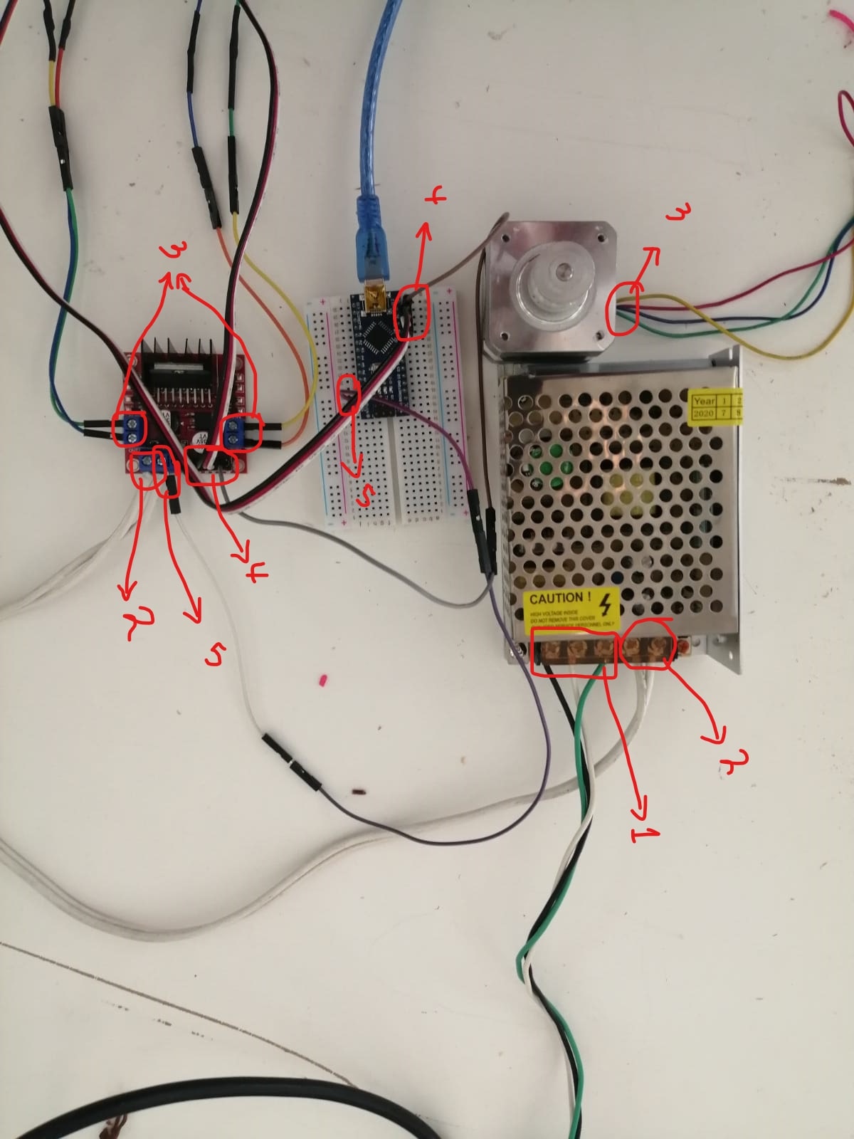
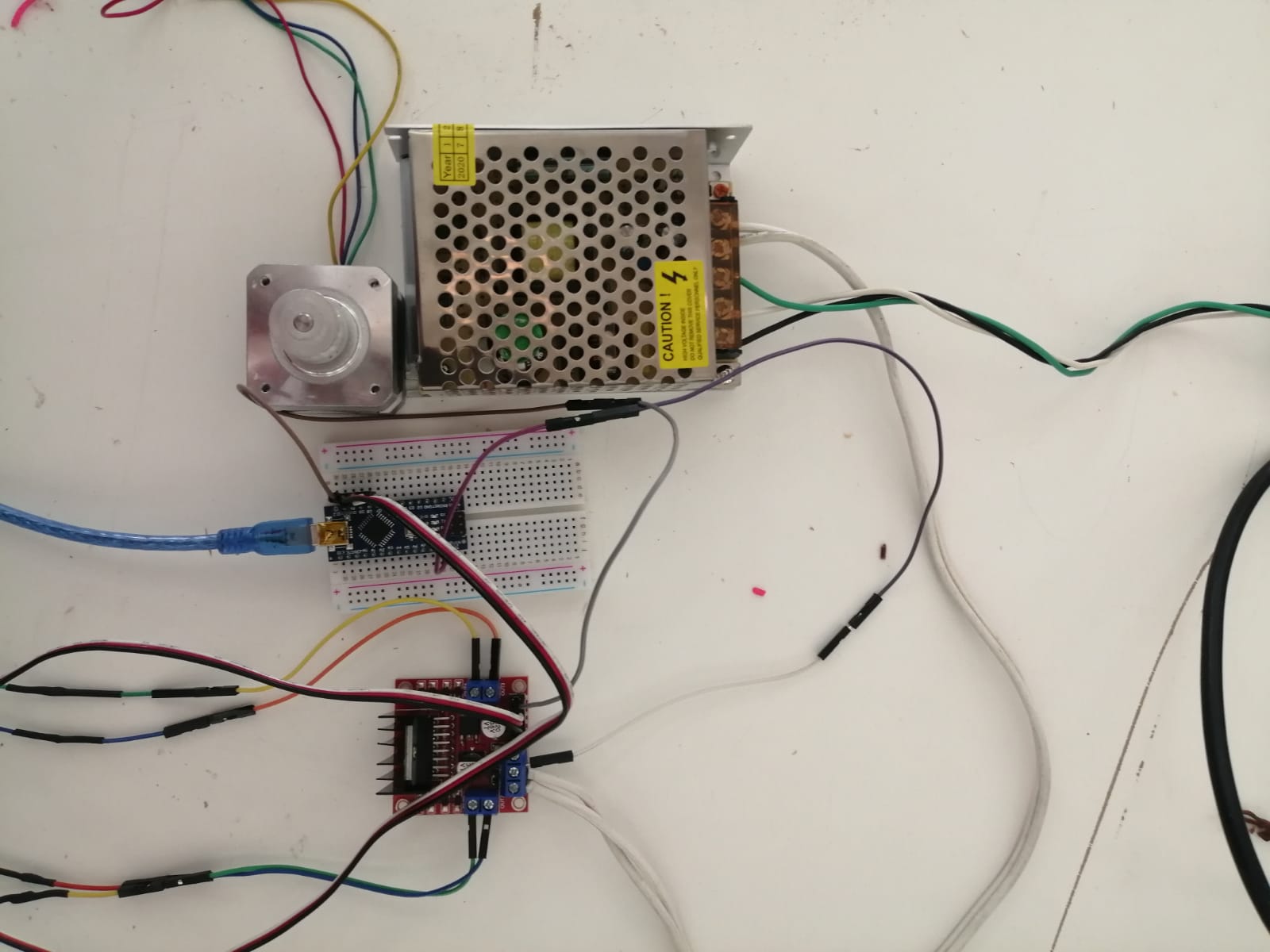
This is picture guide you how to link these part together we put same number about the wires and where you should put them or link them. you should put the Microcontroller on the bread board than start link the wires. Number one are 3 wires L, N, and earth that connecting to the power source to give the s-60-12 power. Number two are two wires V+ and V- that connected to 12V and GND pins and on the same pin GND there is a wire that connected to a pin GND on the Microcontroller which is number five. Number three is 4 wires that come out from the motor if you look carefully you will see that there are two wires come out from a side (Right) and another two wires come from the other side (Left). They are connected to the number 3 on L298N or we can say that the right wires connected with out1 and 2 pins and the left connected with the out3 and 4 pins. Number 4 are 4 wires connected with the pins on the Microcontroller which are pins 8,9,10, and 11 with the 4 pins on the L298N you can see the order of them from the picture because each wire has a colour.
after that we connect the Microcontroller with the laptop and open Arduino program.
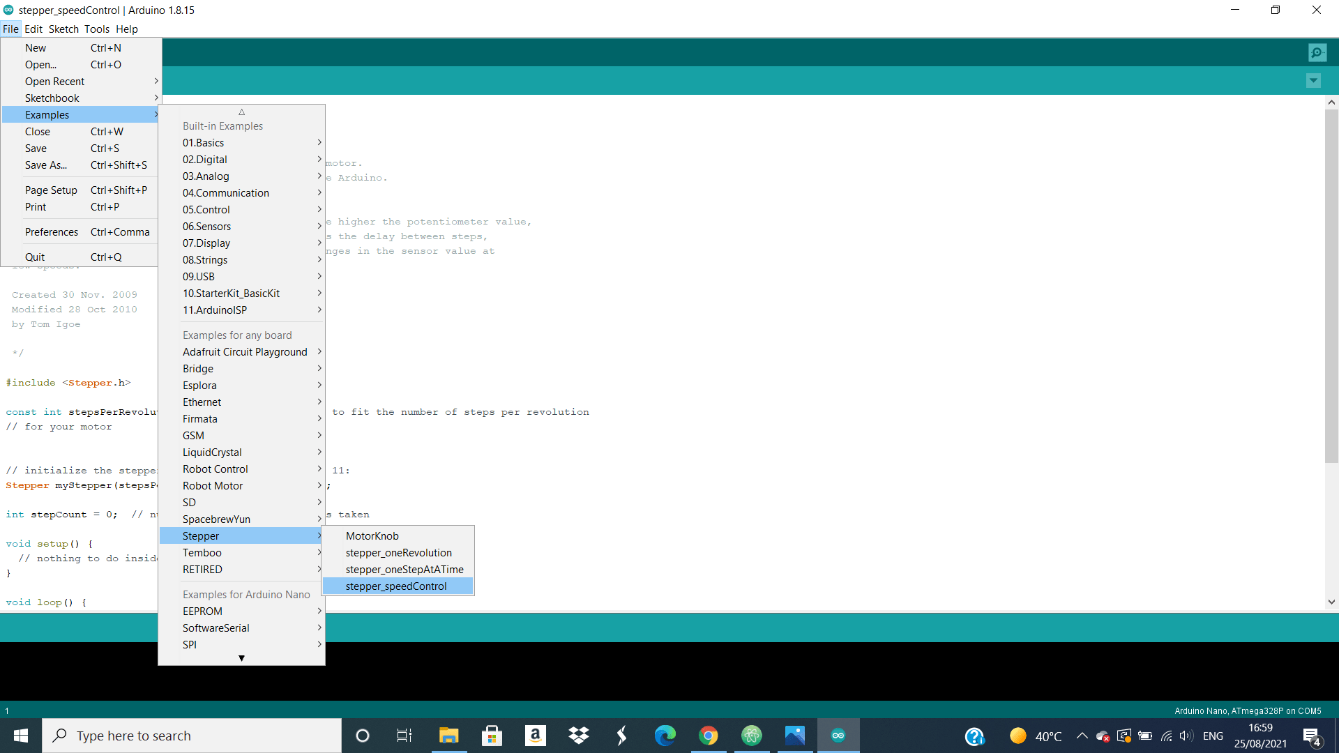 then, click on file option up and go to Examples choice than Stepper this will give you 4 choices we will use the last one because we need to put a specific RPM. We can also download some code from website Control Stepper Motor with L298N Motor Driver & Arduino there is a code for Arduino that make you control not just the RPM also the rotation direction together and also explain how can you connecting the parts that we explain it before.
Finally, they will look like this
then, click on file option up and go to Examples choice than Stepper this will give you 4 choices we will use the last one because we need to put a specific RPM. We can also download some code from website Control Stepper Motor with L298N Motor Driver & Arduino there is a code for Arduino that make you control not just the RPM also the rotation direction together and also explain how can you connecting the parts that we explain it before.
Finally, they will look like this
 and combination the motor with the drill pit and control the RPM from the Arduino and make the drill spin.
Calculations & Results
The calculation needed to do our design is the same as the one we needed to do our first project. But, not all the calculation is determined because our idea of fabricating the design with experimental path.
% Drag flow
W = 0.025 ; %m
H = 0.001 ; %m
D = 0.029 ; %m
N = 1.79 ; %rev/s ( Maximum speed for motor)
theta = 30 ; %degrees ( Screw helix angle ) assumption
meu = 0.6 ; %Pa.s ( assumption )
L = 0.38 ; %m
deltaP = 0 ; % Open discharge
density = 1240000 ; % g/m^3
eta = meu ;
D2 = 1.75*10^-3 ; %m

% Drag flow
Qd = (pi/2)*(W)*(H)*(D)*(N)*(cos(theta))

% Pressure flow rate
Qp = (-W*H^3*(deltaP))/(12*meu*L)

% then, volume flow rate
Q = Qd + Qp  %m^3/s
% flow rate
Qm = (Q*density)/1000  % Kg/s

% Screw characteristics
% Maximum output
% Q = Qmax
Qmax = (1/2)*(pi)^2*(D^2)*N*(sin(theta))*(H)

% P = Pmax and Q = 0 as determined above

P = (6*(pi)*D2*L*N*(eta))/((H^2)*(tan(theta)))


% Material characteristics
% Deborah Number
% Ndeb = tm/tp
E = 3.5 ; % (Young modulus) GPa
% tm = material relaxation time
% tp = processing time
tm = meu/E % seconds
tm_days = tm/86400 % days
tp = 30 ; %estimation (s)
Ndeb = tm / tp


format long e
And The answers in the MATLAB command window are as followed
Qd =

   3.1444e-07


Qp =

     0


Q =

   3.1444e-07


Qm =

   3.8991e-04


Qmax =

  -7.3399e-06


P =

  -2.1018e+03


tm =

    0.1714


tm_days =

   1.9841e-06


Ndeb =

    0.0057

>>